LM729 LM729 17” LCD Monitor User’s Manual By Envision Peripherals, Inc. www.aocmonitor.com .
LM729 TABLE OF CONTENTS Table of Contents For Your Safety Precautions General Notes Before You Operate The Monitor Installation Instructions Operating Instructions Technical Support (FAQ) Appendix 1 2 3 4-5 6 7-13 14-19 20-21 22-25 1
LM729 FOR YOUR SAFETY Before operating the monitor, please read this manual thoroughly. This manual should be retained for future reference. FCC Class B Radio Frequency Interference Statement WARNING: (FOR FCC CERTIFIED MODELS) NOTE: This equipment has been tested and found to comply with the limits for a Class B digital device, pursuant to Part 15 of the FCC Rules. These limits are designed to provide reasonable protection against harmful interference in a residential installation.
LM729 PRECAUTIONS z Do not use the monitor near water, e.g. near a bathtub, washbowl, kitchen sink, laundry tub, swimming pool or in a wet basement. z Do not place the monitor on an unstable cart, stand, or table. If the monitor falls, it can injure a person and cause serious damage to the appliance. Use only a cart or stand recommended by the manufacturer or sold with the monitor. If you mount the monitor on a wall or shelf, use a mounting kit approved by the manufacturer and follow the kit instructions.
LM729 GENERAL NOTES SPECIAL NOTES ON LCD MONITORS The following symptoms are normal with LCD monitor and do not indicate a problem. • • • • • Due to the nature of the fluorescent light, the screen may flicker during initial use. Turn off the Power Switch and then turn it on again to make sure the flicker disappears. You may find slightly uneven brightness on the screen depending on the desktop pattern you use.
LM729 GENERAL NOTES (cont) • Plug & Play DDC 2B Feature - This monitor is equipped with VESA DDC 2B capabilities according to the VESA DDC STANDARD. It allows the monitor to inform the host system of its identity and, depending on the level of DDC used, communicate additional information about its display capabilities. The DDC 2B is a bidirectional data channel based on the I2C protocol. The host can request EDID information over the DDC 2B channel.
LM729 BEFORE YOU OPERATE THE MONITOR FEATURES • • • • • • • 17” (43.
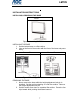
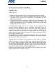
LM729 INSTALLATION INSTRUCTIONS INSTALLING & REMOVING THE BASE Install Figure 1 - Installing the Base. INSTALLING THE BASE 1. Set the bottom base on a flat surface. 2. Line up the front of the monitor with the front of the base and press firmly. Remove Pin Remove Base Figure 2 - Installing the Base. REMOVING THE BASE 1. Never remove the base while the height adjustment lock pin is installed. Set the monitor standing on a flat firm surface. Remove the height adjustment lock pin. 2.
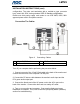
LM729 INSTALLATION INSTRUCTIONS (Cont) POWERCORD Power Source: 1. Make sure that the power cord is the correct type required in your area. 2. This LCD monitor has an internal Universal Power Supply that allows operation in either 100/120V AC or 220/240V AC voltage area (No user adjustment is required.) 3. Connect the AC-power cord into your LCD monitor’s AC-power-input.
LM729 INSTALLATION INSTRUCTIONS (cont) configuration. The other end terminates with a molded-on type connector body, rated 10A, 250V, having standard CEE-22 female configuration. Please note that power supply cord needs to use VDE 0602, 0625, 0821 approval power cord in European counties. Connecting The Cables Figure 2 1. 2. 15-pin D-SUB Cable Audio cable Connecting Cables 3. AC Power Cord Turn off your computer before performing the procedure below. 1.
LM729 INSTALLATION INSTRUCTIONS (cont) How To Install The INF & ICM Files • This is a Plug & Play monitor. Microsoft Windows will automatically install a Plug & Play driver for it when you first install this monitor. It is not necessary to install the INF driver file included in the floppy diskette or CD if Microsoft Windows successfully installed a Plug & Play driver.
LM729 INSTALLATION INSTRUCTIONS (cont) Height, Tilt, Pivot & Swivel Adjustment Your monitor features a multi-adjustable stand that will enable it move 110mm up/down (height adjustment), 25 degree forward/backward (tilt adjustment), 90 degree landscape/portrait (pivot adjustment – note: The monitor must be in adjusted to it’s highest position before rotating it.) and 70 degree side/side (swivel adjustment).
LM729 INSTALLATION INSTRUCTIONS (cont) Preparing To Install The Optional Wall Mount Arm (Not Included) This monitor can be attached to a wall mounting arm you can purchase separately. Turn the power OFF then dis-connect the cables from the monitor before performing the procedure below. Lay the monitor face down on a soft surface. 1. 2. 3. 4. Remove the two rubber screw covers. Remove the 2 screws that hold the plastic hinge cover. Remove the plastic hinge cover. Remove the small plastic cover.
LM729 INSTALLATION INSTRUCTIONS (cont) Attaching The Optional Wall Mount Arm (not supplied) Follow these steps to finish installing the wall mounting arm: 1. 2. 3. Place the wall mounting arm onto the back of the monitor. Line up the holes of the arm with the holes in the back of the monitor. Insert the 4 screws into the holes and tighten. Reconnect the cables. Refer to the user’s manual that came with the optional wall mounting arm for instrucstions on attaching it to the wall.
LM729 OPERATING INSTRUCTIONS EXTERNAL CONTROLS Figure 4 - External Controls 1. Power Button 2. MENU or ENTER Button 3. > or Volume Button 4. < or Volume Button 5. Auto Adjust or Exit Button . Power Button: Press this button to turn the monitor ON or OFF. . MENU / ENTER: This button will activate the OSD menu when OSD is OFF or activate/de-activate an adjustment function when OSD is ON or Exit OSD menu when in Volume Adjust OSD status.
LM729 OPERATING INSTRUCTIONS (cont) • Auto Adjust button / Exit: 1. 2. When OSD menu is in active status, this button will act as EXIT-KEY (EXIT OSD menu) or go back to the previous menu. When OSD menu is in off status, press this button for 2 seconds to activate the Auto Adjustment function. The Auto Adjustment function is used to set the HPos, VPos, Clock and Focus. • Power Indicator: Green Orange — — Power On mode. Off mode.
LM729 OPERATING INSTRUCTIONS (cont) How To Adjust A Setting 1. Press the MENU-button to activate the OSD window (Figure 4). 2. Press < or > to navigate through the functions. Once the desired function is highlighted, press the MENU-button to activate it. If the function selected has a sub-menu, press < or > again to navigate through the sub-menu functions. Once the desired function is highlighted, press MENU-button to activate it. 3. Press < or > to change the settings of the selected function. 4.
LM729 OPERATING INSTRUCTIONS (cont) The table below describes the fuction of each OSD icon. Main Menu Item Lumina nce Image Setup Main Sub Menu Menu Item Icon Sub Menu Icon Contrast from Digital-register. Recall Cool Contrast Value Brightness Backlight Adjustment Recall Cool Brightness Value Focus Adjust Picture Phase to reduce Horizontal-Line noise Adjust picture Clock to reduce Vertical-Line noise. Adjust the horizontal position of the picture. Adjust the verticalposition of the picture.
LM729 OPERATING INSTRUCTIONS (cont) Main Menu Item Main Sub Menu Menu Item Icon Sub Menu Icon Auto Config Yes N/A No N/A OSD Setup N/A Auto Adjust the H/V Position, Focus and Clock of picture. N/A Do not execute Auto Config, return to main menu. 50 Adjust the horizontal position of the OSD. H. Position 50 Adjust the verticalposition of the OSD. Adjust the OSD 10 timeout. V.
LM729 OPERATING INSTRUCTIONS (cont) Main Menu Item Informati on Reset Exit Main Menu Icon Sub Menu Item Sub Menu Icon Informati on N/A Yes N/A No N/A N/A N/A Description Show the resolution, H/V frequency and input port of current iput timing. Clear each old status of Autoconfiguration and set the color temperature to Cool. Do not execute reset, return to main menu.
LM729 TECHNICAL SUPPORT (FAQ) Problem & Question Power LED is not on No Plug & Play Picture is fuzzy Picture bounces or a wave pattern is present in the picture The power LED is ON (Orange)but there’s no video or no picture. Missing one of the primary colors (RED, GREEN, or BLUE) Screen image is not centered or sized properly.
LM729 TECHNICAL SUPPORT (FAQ) (cont) CLOCK (pixel frequency) controls the number of pixels scanned by one horizontal sweep. If the frequency is not correct, the screen shows vertical stripes and the picture has not correct width. FOCUS adjusts the phase of the pixel clock signal. With a wrong phase adjustment the picture has horizontal disturbances in light picture. For FOCUS and CLOCK adjustment use “dot-pattern” or win 95/98 shut-down mode pattern.
LM729 APPENDIX Specifications Driving system TFT Color LCD LCD Panel Size 43.2cm(17.0") Pixel pitch 0.264mm( H )x 0.264mm( V ) Viewable angle 140° (H) 140° (V) Input Display Colors Dot Clock Max. Resolution Plug & Play EPA ENERGY STAR® Video H-Frequency V-Frequency R,G,B Analog Interface 30KHz –83KHz 55-75Hz 16.2M Colors 135MHz 1280 x 1024 @75Hz VESA DDC 2BTM İ42W İ2W D-Sub 15pin Analog:0.7Vp-p(standard), 75 OHM, Positive Horizontal : 337.92mm Vertical : 270.
LM729 APPENDIX (cont) • • • • • • • • • • • • • • • • • • Switch External Controls: Auto Adjust Key / Volume Power Button MENU/ Exit Contrast Brightness Focus Clock H.Position V.
LM729 APPENDIX (cont) Preset Display Modes RESOLUTION HORIZONTAL FREQUENCY(KHZ) 640 × 480 31.469 59.940 640 × 480 37.500 75.000 800 × 600 37.879 60.317 800 × 600 46.875 75.000 1024 × 768 48.363 60.004 1024 × 768 56.476 70.069 1024 x 768 60.023 75.029 1280 × 1024 64.00 60.000 1280 × 1024 80.00 75.000 DOS 720 x 400 31.469 70.087 XGA 1024 x 768 48.780 60.001 1024 × 768 60.241 74.
LM729 APPENDIX (cont) Connector Pin Assignment 1 5 6 10 11 15 15 - Pin D-Sub Connector PIN NO. DESCRIPTION PI N NO. DESCRIPTION 1. 2. 3. 4. 5. 6. 7. 8. Red Green Blue Monitor Ground DDC-return R-Ground G-Ground B-Ground 9. 10. 11. 12. 13. 14. 15.