
User Guide


64
A
A
K
K
7
7
7
7
-
-
3
3
3
3
3
3
O
O
n
n
l
l
i
i
n
n
e
e
M
M
a
a
n
n
u
u
a
a
l
l
L
L
a
a
y
y
o
o
u
u
t
t
(
(
F
F
r
r
e
e
q
q
u
u
e
e
n
n
c
c
y
y
I
I
s
s
o
o
l
l
a
a
t
t
i
i
o
o
n
n
W
W
a
a
l
l
l
l
)
)
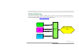
For high frequency operation, especially overclocking,
layout is the most important factor to make sure
chipset and CPU working in stable condition. The
layout of this motherboard implements AOpen’s
unique design called “ Frequency Isolation Wall”.
Separating each critical portion of motherboard into
regions where each region operates in a same or
similar frequency range to avoid cross talk and
frequency interference between each region’s
operations and condition. The trace length and route
must be calculated carefully. For example, the clock
trace must be equal length (not necessarily as short
as possible) so that clock skew will be controlled
within few a pico second (1/10
12
Sec)
Note: This diagram is for example only, it may not exactly be the same diagram of this motherboard.