
User Guide


Table Of Contents
- AK79G-V/AK79G-VN/AK79D-1394/A79G-1394
- Hardware Installation
- About ¡§Manufacturer Upgrade Optional¡¨ and ¡§User Upgrade Optional
- JP14 Clear CMOS Data
- CPU Installation
- AOpen Overheat Protection (O.H.P.) Technology
- Full-range Adjustable CPU Core Voltage
- Setting CPU Frequency
- Supported CPU Frequency
- CPU and Housing Fan Connector
- JP27/28 Keyboard/Mouse Wakeup Jumpers
- DIMM Sockets (128-Bit DDR Dual Channel)
- STBY LED
- Front Panel Connector
- ATX Power Connector
- AC Power Auto Recovery
- IDE and Floppy Connector
- S/PDIF Connector (for AK79D-1394 and AK79G-1394)
- Super 5.1 Channel Audio Effect
- TV Output Connector (for AK79G-V, AK79G-VN and AK79G-1394)
- IrDA Connector
- AGP (Accelerated Graphic Port) 8X Expansion Slot
- AGP Protection Technology and AGP LED
- Support 10/100 Mbps LAN Onboard (For AK79G-VN, AK79D-1394 and AK79G-1394)
- CNR (Communication and Network Riser) Expansion Slot
- Game Port Bracket Supported
- Color Coded Back Panel
- COM2 Connector
- Support Six USB Connectors
- IEEE 1394 Connectors (for AK79D-1394 and AK79G-1394)
- Case Open Connector
- CD Audio Connector
- AUX-IN Connector
- Front Audio Connector
- Battery-less and Long Life Design
- CPU Over-current Protection
- AOConfig Utility
- Resetable Fuse
- 2200£gF Low ESR Capacitor
- Enlarged Aluminum Heatsink
- Open JukeBox Player
- Vivid BIOS technology
- The noise is gone!! ---- SilentTek
- Driver and Utility
- Phoenix Award BIOS
- Glossary
- AC97 CODEC
- ACPI (Advanced Configuration & Power Interface)
- ACR (Advanced Communication Riser)
- AGP (Accelerated Graphic Port)
- AMR (Audio/Modem Riser)
- ATA (AT Attachment)
- BIOS (Basic Input/Output System)
- Bluetooth
- CNR (Communication and Networking Riser)
- DDR (Double Data Rate) RAM
- ECC (Error Checking and Correction)
- EEPROM (Electronic Erasable Programmable ROM)
- EPROM (Erasable Programmable ROM)
- EV6 Bus
- FCC DoC (Declaration of Conformity)
- FC-PGA (Flip Chip-Pin Grid Array)
- FC-PGA2 (Flip Chip-Pin Grid Array)
- Flash ROM
- Hyper Threading
- IEEE 1394
- Parity Bit
- PCI (Peripheral Component Interface) Bus
- PDF Format
- PnP (Plug and Play)
- POST (Power-On Self Test)
- PSB (Processor System Bus) Clock
- RDRAM (Rambus Dynamic Random Access Memory)
- RIMM (Rambus Inline Memory Module)
- SDRAM (Synchronous DRAM)
- SATA (Serial ATA)
- SMBus (System Management Bus)
- SPD (Serial Presence Detect)
- USB 2.0 (Universal Serial Bus)
- VCM (Virtual Channel Memory)
- Wireless LAN ¡V 802.11b
- ZIP file
- Troubleshooting
- Technical Support
- Product Registration
- How to Contact Us
29
A
A
K
K
7
7
9
9
G
G
-
-
V
V
/
/
A
A
K
K
7
7
9
9
G
G
-
-
V
V
N
N
/
/
A
A
K
K
7
7
9
9
D
D
-
-
1
1
3
3
9
9
4
4
/
/
A
A
K
K
7
7
9
9
G
G
-
-
1
1
3
3
9
9
4
4
O
O
n
n
l
l
i
i
n
n
e
e
M
M
a
a
n
n
u
u
a
a
l
l
D
D
I
I
M
M
M
M
S
S
o
o
c
c
k
k
e
e
t
t
s
s
(
(
1
1
2
2
8
8
-
-
B
B
i
i
t
t
D
D
D
D
R
R
D
D
u
u
a
a
l
l
C
C
h
h
a
a
n
n
n
n
e
e
l
l
)
)
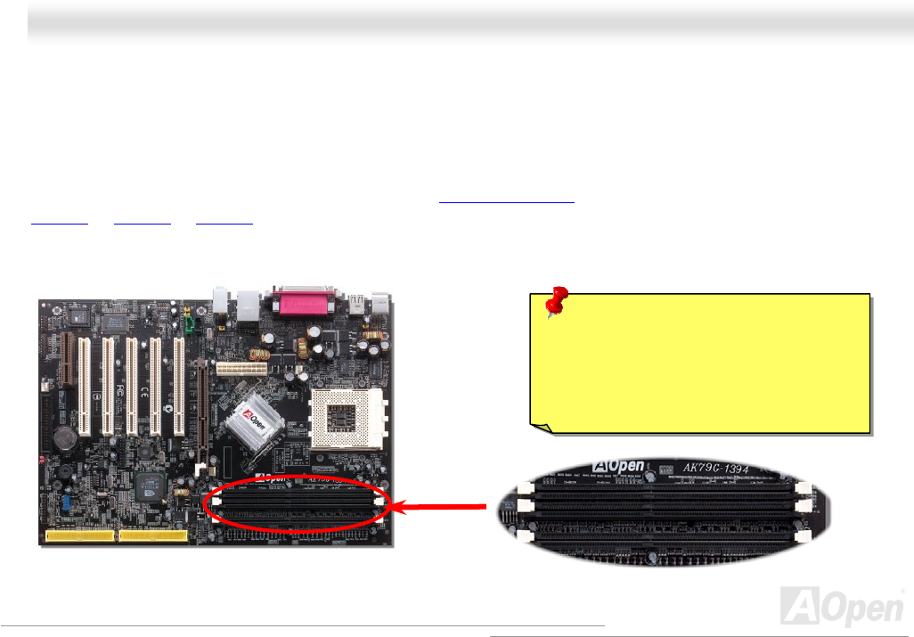
In the past, we used to have 64-bit memory bandwidth for memory access. No matter how many memory modules have been
installed, though capacity added, the speed of access remains the same. With 128-bit dual channel introduced, it doubles the
memory bandwidth up to 5.4GB in advanced 128-bit mode.
This motherboard supports DDR400/333/266 with Maximum capacity up to 3GB (When enabling VGA onboard, memory can run
max. up to 333MHz). This motherboard has three 184-pin DDR DIMM sockets
that allow you to install 128-bit dual channel
DDR400
or DDR333 or DDR266 memory up to 3GB. Only Non-ECC DDR RAM is supported, otherwise, it will cause serious
damage on memory sockets or SDRAM module. For over clocking purpose, you can adjust memory voltage in BIOS from 2.5V
to 2.65V.
DDR
RAM
Warning: This motherboard supports DDR
RAM. Please do not install the SDRAM on
the DDR RAM sockets, otherwise, it will
cause serious damage on memory sockets
or SDRAM module.