
User Guide


Table Of Contents
- AK79G-V/AK79G-VN/AK79D-1394/A79G-1394
- Hardware Installation
- About ¡§Manufacturer Upgrade Optional¡¨ and ¡§User Upgrade Optional
- JP14 Clear CMOS Data
- CPU Installation
- AOpen Overheat Protection (O.H.P.) Technology
- Full-range Adjustable CPU Core Voltage
- Setting CPU Frequency
- Supported CPU Frequency
- CPU and Housing Fan Connector
- JP27/28 Keyboard/Mouse Wakeup Jumpers
- DIMM Sockets (128-Bit DDR Dual Channel)
- STBY LED
- Front Panel Connector
- ATX Power Connector
- AC Power Auto Recovery
- IDE and Floppy Connector
- S/PDIF Connector (for AK79D-1394 and AK79G-1394)
- Super 5.1 Channel Audio Effect
- TV Output Connector (for AK79G-V, AK79G-VN and AK79G-1394)
- IrDA Connector
- AGP (Accelerated Graphic Port) 8X Expansion Slot
- AGP Protection Technology and AGP LED
- Support 10/100 Mbps LAN Onboard (For AK79G-VN, AK79D-1394 and AK79G-1394)
- CNR (Communication and Network Riser) Expansion Slot
- Game Port Bracket Supported
- Color Coded Back Panel
- COM2 Connector
- Support Six USB Connectors
- IEEE 1394 Connectors (for AK79D-1394 and AK79G-1394)
- Case Open Connector
- CD Audio Connector
- AUX-IN Connector
- Front Audio Connector
- Battery-less and Long Life Design
- CPU Over-current Protection
- AOConfig Utility
- Resetable Fuse
- 2200£gF Low ESR Capacitor
- Enlarged Aluminum Heatsink
- Open JukeBox Player
- Vivid BIOS technology
- The noise is gone!! ---- SilentTek
- Driver and Utility
- Phoenix Award BIOS
- Glossary
- AC97 CODEC
- ACPI (Advanced Configuration & Power Interface)
- ACR (Advanced Communication Riser)
- AGP (Accelerated Graphic Port)
- AMR (Audio/Modem Riser)
- ATA (AT Attachment)
- BIOS (Basic Input/Output System)
- Bluetooth
- CNR (Communication and Networking Riser)
- DDR (Double Data Rate) RAM
- ECC (Error Checking and Correction)
- EEPROM (Electronic Erasable Programmable ROM)
- EPROM (Erasable Programmable ROM)
- EV6 Bus
- FCC DoC (Declaration of Conformity)
- FC-PGA (Flip Chip-Pin Grid Array)
- FC-PGA2 (Flip Chip-Pin Grid Array)
- Flash ROM
- Hyper Threading
- IEEE 1394
- Parity Bit
- PCI (Peripheral Component Interface) Bus
- PDF Format
- PnP (Plug and Play)
- POST (Power-On Self Test)
- PSB (Processor System Bus) Clock
- RDRAM (Rambus Dynamic Random Access Memory)
- RIMM (Rambus Inline Memory Module)
- SDRAM (Synchronous DRAM)
- SATA (Serial ATA)
- SMBus (System Management Bus)
- SPD (Serial Presence Detect)
- USB 2.0 (Universal Serial Bus)
- VCM (Virtual Channel Memory)
- Wireless LAN ¡V 802.11b
- ZIP file
- Troubleshooting
- Technical Support
- Product Registration
- How to Contact Us
32
A
A
K
K
7
7
9
9
G
G
-
-
V
V
/
/
A
A
K
K
7
7
9
9
G
G
-
-
V
V
N
N
/
/
A
A
K
K
7
7
9
9
D
D
-
-
1
1
3
3
9
9
4
4
/
/
A
A
K
K
7
7
9
9
G
G
-
-
1
1
3
3
9
9
4
4
O
O
n
n
l
l
i
i
n
n
e
e
M
M
a
a
n
n
u
u
a
a
l
l
F
F
r
r
o
o
n
n
t
t
P
P
a
a
n
n
e
e
l
l
C
C
o
o
n
n
n
n
e
e
c
c
t
t
o
o
r
r
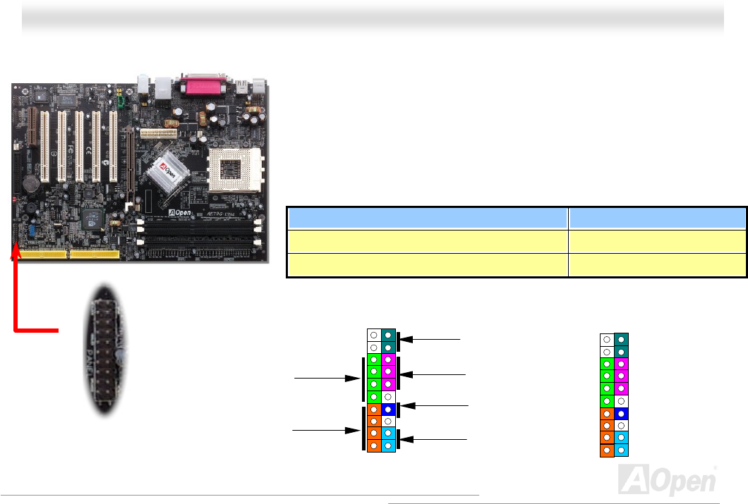
Suspend Type ACPI LED
Power on Suspend (S1) or Suspend to RAM (S3) Blinking between green and red.
Suspend to Disk (S4) The LED will be turned off
Attach the power LED, speaker, power and reset switch connectors to th
e
corresponding pins. If you enable “Suspend Mode” item in BIOS Setup, the ACPI
& Power LED will keep flashing while the system is in suspend mode.
Locate the power switch cable from your ATX housing. It is 2-pin female
connector from the housing front panel. Plug this connector to the soft-power
switch connector marked SPWR.
1
SPWR
GND
ACPI LED-
GND
ACPILED
NC
ACPI_B
GND
RESET
GND
NC
NC
+5V
IDE LED
IDE LED
+5V
+5V
GND
NC
SPEAKER
1
Speaker
IDE LED
SPWR
ACPI & PWR
LED
Reset
ACPI LED
(
Blue
)