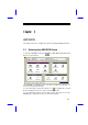
Chapter 3 AMI BIOS This chapter tells how to configure the system by setting the BIOS parameters. 3.1 Entering the AMI BIOS Setup To enter the AMI BIOS Setup, press appears as shown below. . The AMI BIOS Setup Main Menu The AMI BIOS is in Windows form. You can use either the keyboard or a mouse to move between the items. To select among the Setup menu groups, use to highlight the selected group or simply click on the icon of the selected Setup menu.
AMI BIOS Utility After making your selection, press the selected menu option. You may press or double-click on the icon to open to perform the following: • Resolve an address conflict due to an IRQ address assigned to multiple slots. For more information on IRQ assignment, see the section 3.2.3 (Chipset Features Setup). • Return to the BIOS default settings if the PnP BIOS does not recognize the hardware modifications under Windows 95.
AMI BIOS Utility 3.2 Setup Menu The figure below shows the Setup window. Use the arrow keys to highlight an option. 3.2.1 Standard Setup The following screen appears if you select options: Standard from the Setup You can input configuration values such as date, time and disk types in this menu. PRIMARY MASTER AND SLAVE/ SECONDARY MASTER AND SLAVE These parameters allow you to configure the hard disks and the IDE devices connected to your IDE connectors.
AMI BIOS Utility To configure the hard disk connected to the slave port of the primary IDE connector, select Primary Slave. The secondary IDE connector also supports two IDE devices. To configure the hard disk or the IDE device connected to the master port, select Secondary Master. Choose Secondary Slave to configure the device connected to the slave port.
AMI BIOS Utility Type This parameter lets you set the IDE device type that your system supports. The options are User, Auto, CD-ROM, Type 1-46, and Not Installed. Select Auto to automatically configure the installed hard disk or IDE device. Select CD-ROM if you have a CD-ROM installed in your system. If you have an old type HDD installed, you may need to enter the HDD parameters manually. To do this, you must set this parameter to User. Select Not Installed to bypass the function.
AMI BIOS Utility 32-bit Mode Enabling this parameter improves system performance by increasing the hard disk access to 32-bit mode. However, make sure that your hard disk supports this function before you enable the parameter. Otherwise, set this parameter to Off. PIO Mode Setting this parameter to On allows the system to use a faster hard disk drive. If your hard disk does not support the PIO mode feature, set this parameter to Off.
AMI BIOS Utility Select the arrow keys to move among the items. Press or click on or to set the current time and date. Press or double-click on the Control menu box at the upper-left corner of the window. FLOPPY DRIVES A AND B To configure the first floppy drive, select Floppy A. The following values appear on screen: After selecting the proper setting, press Select Floppy floppy drive. . B and follow the same procedure to configure the second 3.2.
AMI BIOS Utility The first screen does not show all the parameters of the Advanced Configuration menu. To scroll down the rest of the parameters, press . Press or to highlight the desired parameter.
AMI BIOS Utility Do not change the settings of the Advanced Setup parameters if you are not a qualified technician. Doing so may cause fatal system failure. Quick Boot During boot up, the system performs power-on self test (POST) routines. Enable the parameter if you want to skip some POST routines during the boot process. Set this to Disabled to let the system perform all the POST routines and follow the specified boot-up sequence.
AMI BIOS Utility Floppy Drive Swap This parameter allows you to swap floppy drives. For example, if you have two floppy drives (A and B), you can assign the first drive as drive B and the second drive as drive A or vice-versa. Disable the parameter to bypass the function. The default is Disabled. Floppy Drive Seek When enabled, BIOS detects whether there is a floppy disk drive installed in the system. Disable the parameter to skip the function.
AMI BIOS Utility Internal Cache This function lets you enable or disable the internal cache. External Cache This function lets you enable or disable the external cache. System BIOS Cacheable Enabling this parameter allows you to cache the system BIOS to further system performance. The default settings is Enabled. C000 ~ DC00, 16K Shadow These parameters are for shadowing expansion cards with ROM.
AMI BIOS Utility 3.2.3 Chipset Features Setup The Chipset Features Setup controls the board chipset settings. The controls for this menu are the same as for the previous screens. The Chipset Features Setup screen appears as follows. To scroll down the rest of the parameters, press highlight the desired parameter. . Use or to Memory Hole This option lets you assign the system memory area for ISA cards installed in your system to avoid memory conflicts.
AMI BIOS Utility DRAM Timing Setting The selections for this parameter are 60 ns, 70 ns, and Manual. If you select either 60 ns or 70 ns, the DRAM Timing subparameters become non-configurable since BIOS automatically sets the values. Select Manual if you want to specify your own parameter settings. FAST MA TO RAS# DELAY This option specifies the wait state between the master address (MA) and row address strobe (RAS) signals. The selections are 1 clock and 2 clocks.
AMI BIOS Utility REFRESH RAS# ASSERTION This function controls the number of clocks required to assert RAS# for refresh cycles. The available settings are 4 clocks and 5 clocks. FAST EDO PATH SELECT Enable this option to select a fast path for CPU to DRAM read cycles to minimize the lead-off time. This is applicable only for EDO DRAMs. For other DRAM types, we recommend that you set this to Disabled.
AMI BIOS Utility PCI 2.1 Compliant This parameter lets you enable or disable the PIIX3 PCI register passive release functions. When enabled , the PIIX3 controls the USB operation to make sure that the system complies with the PCI Revision 2.1 specification. Select Disabled to disregard the functions. USB Function Enabled This parameter lets you enable or disable the USB device(s) connected to your system, if any. The default is Disabled. The USB function shares INTD with PCI slot 4.
AMI BIOS Utility 3.2.4 Power Management Setup To take advantage of the power-management feature, select Power Management from the Setup menu. The following screen appears: To scroll down the rest of the parameters, press highlight the desired parameter. . Use or to Power Management/APM This parameter enables or disables the advanced power-management function.
AMI BIOS Utility Instant On Time-out (Minutes) This parameter is configurable only if the Power Management/APM parameter is set to Instant On. This option lets you specify when to resume system power after being in power-saving mode for a certain period of time. Green Monitor Power-down State This function lets you set when to power down your green PC monitor. The options are Standby, Suspend, and Off. The default is Standby.
AMI BIOS Utility Slow Clock Ratio When the system enters the standby mode, the CPU clock starts to slow down. This parameter lets you set the “slow down” clock ratio. The selections are from 1:1, 1:2, 1:4, 1:8, 1:16, 1:32, 1:64, and 1:128. Display Activity This function lets you check the activity of the monitor. When set to Monitor, any detected activity from the display resumes the system to normal mode. When set to Ignore, the power management function bypasses the display activities detected.
AMI BIOS Utility 3.2.5 PCI/PnP Setup The PCI/PNP Setup allows you to specify the setting for your PCI devices. The screen below appears on screen if you select PCI/PnP from the Setup menu. To scroll down the rest of the parameters, press highlight the desired parameter. . Use or to Plug-and-Play Aware O/S Enable this parameter only if you have a Plug-and-Play operating system, such as Windows 95.
AMI BIOS Utility PCI IRQ Priority Auto Setting Set this parameter to Yes to automatically set the appropriate available interrupt for each PCI slot. Select No if you prefer to manually set the interrupts. 1st, 2nd, 3rd, and 4th Available IRQ These parameters are configurable only if the PCI IRQ Priority Auto Setting parameter is set to No. When configurable, these let you specify the ranking of the interrupts which you can assign to the PCI devices installed in your system.
AMI BIOS Utility Reserved Memory Size for ISA This option lets you specify the memory area reserved for Legacy/ISA devices. Reserved Memory Base for ISA This option lets you specify the memory base address reserved for Legacy/ISA devices.
AMI BIOS Utility 3.2.6 Peripheral Setup Select Peripheral from the Setup menu and the following screen appears. Onboard FDC This parameter enables or disables the floppy drive controller. Onboard Serial Port 1 This parameter allows you to select the address for the first serial port. The available settings are Auto, 3F8h, 2F8h, 3E8h, 2E8h, and Disabled. Selecting Disabled deactivates the port. Onboard Serial Port 2 This parameter allows you to select the address for the second serial port.
AMI BIOS Utility • HPSIR - Select this setting only if the InfraRed (IR) function is activated (i.e., an IR module is installed in your system). This setting allows infrared serial communication at a maximum baud rate of 115K baud. • ASKIR - Select this setting only if the IR function is activated (i.e., an IR module is installed in your system). This setting allows infrared serial communication at a maximum baud rate of 19.2K baud.
AMI BIOS Utility 3.3 Security Setup The Security window contains the password and anti-virus features. 3.3.1 Supervisor Password The use of password prevents unauthorized use of your computer. If you set a Supervisor password, the system prompts for this password before granting access to Setup or system boot, depending on the Password Check setting in the Advanced CMOS Setup menu. To set a Supervisor password, select window.
AMI BIOS Utility 1. Type in a six-character password using letters, numbers, or a combination of both. When you type the characters, they appear as asterisks on the password screen boxes. 2. Press . 3. Retype the password when a password confirmation box appears asking you to retype the password. You may also use the mouse and the characters on the screen to set up a password. 1. Click on six characters from the password screen. appear on the boxes as asterisks. 2. Click on . 3.
AMI BIOS Utility Setup. 3.3.3 Anti-virus Select Anti-Virus from the Security window to display the following option box. The virus protection options allow you to enable or disable the virus protection feature.
AMI BIOS Utility 3.4 Utility Setup The Utility window lets you change WinBIOS Setup colors and language setting. 3.4.1 Color Set Select Color Set from the Utility window to display the following screen. Use the arrow keys or simply click an option to select your desired background color for WinBIOS. 3.4.2 Language Select Language from the Utility window to display the following screen. The system language currently supported is only English. option is non-configurable and is for display only.
AMI BIOS Utility 3.5 Default Setup The Default window allows you to select a group of settings for all WinBIOS Setup options. 3.5.1 Original When you select Original, a dialog box prompts you to restore the original BIOS default values. Select No to keep your current settings. Select Yes to restore the original values. 3.5.2 Optimal When you select Optimal, a dialog box prompts you to load the values that will help your system deliver optimum performance. Select Yes to load the BIOS optimum values.
AMI BIOS Utility 3.5.3 Turbo When you select Turbo, a dialog box prompts you to load the Turbo values to further enhance system performance. Select Yes to load the Turbo values. Select No to keep your current settings.
AMI BIOS Utility 3.6 Exiting Setup Carefully check your new settings when you have finished configuring the system. If correct, write them down and keep the recorded values in a safe place. If in the future, the battery loses power or the CMOS chip is damaged, you will know what values to enter when you rerun setup. Press to display the following screen. Press or , then or simply click on an option to select. Select Save changes and Exit to save the changes that you made.
AMI BIOS Utility 3.7 NCR SCSI BIOS and Drivers The NCR 53C810 SCSI BIOS resides on the same flash memory chip as the system BIOS. To use the onboard NCR BIOS, you need to install an NCR 53C810 SCSI controller card in your system. All SCSI devices that you install in your system require software drivers. The NCR SCSI BIOS directly supports SCSI hard disks under DOS, Windows and OS/2.