
User Guide
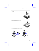

Hardware Installation
2-2
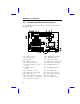
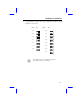
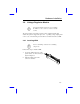
2.2 Jumper and Connector Locations
The following figure shows the locations of the jumpers and connectors on
the system board:
CN1: COM1 connector CN16: Multifunction connector
CN2: Power connector CN17: HDD LED connector
CN3: IR connector JP1: CMOS setting jumper
CN6: COM2 connector JP2: CPU frequency select jumper
CN7: Parallel port connector JP3: PS/2 mouse select jumper
CN8: Floppy disk drive connector JP4: I/O DMA channel select
jumper
CN9: IDE1 connector JP5: I/O DMA channel select
jumper
CN10: PS/2 mouse connector JP6: I/O controller jumper
CN11: USB connector (optional) JP7: CPU type select jumper
CN12: IDE2 connector JP8: CPU voltage select jumper
CN13: CPU frequency select jumper JP9: Reserved jumper
CN14: CPU frequency select jumper JP10: Two-pin fan connector
CN15: Keyboard clock jumper