
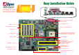
User Guide
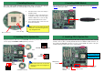

1. Pull up the CPU socket lever and up to
90-degree angle.
2. Locate Pin 1 in the socket and look fo
r
a (golden) cut edge on the CPU uppe
r
interface. Match Pin 1 and cut edge.
Then insert the CPU into the socket.
3. Press down the CPU socket lever and
finish CPU installation.
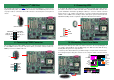
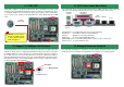
Plug in the CPU fan cable to the 3-pin CPU FAN connector. If you have chassis fan, you
can also plug it on SYSFAN2 or FAN3 (AUX Fan) connector.
5. Installing DIMM Module
This motherboard has two 184-pin DDR DIMM sockets that allow you to install DDR200 o
r
DDR266
memory up to 2GB.
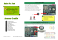
3. Installing Processor
Note: If you do not match the CPU
socket Pin 1 and CPU cut edge well, it
may damage the CPU.
CPU socket lever
CPU cut edge
Note: Some CPU fans do not have
sensor pin so they cannot support fan
monitoring.
CPUFAN Connector
4. Installing CPU & System Fan
SYSFAN1 Connector
This socket supports Micro-FC-PGA2 package CPU, which is the latest CPU package
developed by Intel. Other forms of CPU package are impossible to be fitted in.
SYSFAN2 Connector
GND
+12V
SENSOR
GND
SENSOR
+12V
GND
+12V
SENSOR
DIMM1
DIMM2
6. Installing CPU & System Fan
Connect 34-pin floppy cable and 40-pin IDE cable to floppy connector FDC and IDE
connector. Pin1 of cable is normally marked with red color. Addition to IDE connectors, we
also provide two RAID IDE connectors for you to connect RAID. Be careful of the pin1
orientation. Wrong orientation may cause system damage.
IDE Secondary (2nd)
IDE Primary (1st)
ATA 66/100 IDE
Connector
FDD Connector
RAID secondary
channel
RAID primar
y
channel