
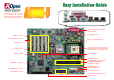
User Guide

RTS#
RI#
GND
SOUT
DCD#
USBPWR0
USB_FP_P0-
USB_FP_P0+
GND
KE
Y
USBPWR0
USB_FP_P1-
USB_FP_P1+
GND
NC
1 2
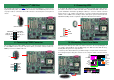
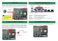
9. Connecting WOL
10. Connecting Front Panel Cable
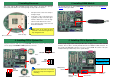
8. Connecting COM2 Connector
This motherboard comes with a COM1 connector on the back panel. However, we provide
an extra COM2 connector for your convenience. Once you need to connect a device via
COM2, just connect a suitable cable on it.
To use Wake On LAN function, you must have a network card with chipset that supports
this feature, and connect a cable from LAN card to motherboard WOL connector. The
system identification information (probably IP address) is stored on network card and
because there is a lot of traffic on the Ethernet, you need to install network managemen
t
software, such as ADM, for the checking of how to wake up the system. Note that, at least
600mA ATX standby current is required to support the LAN card for this function.
Attach the power LED, speaker, and reset switch connectors to the corresponding pins. If
you enable “Suspend Mode” item in BIOS Setup, the ACPI & Power LED will keep
flashing while the system is in suspend mode.
Locate the power switch cable from your ATX housing. It is 2-pin female connector from
the housing front panel. Plug this connector to the soft-power switch connector marked
SPWR.
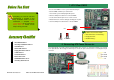
7. Support 2
nd
USB Port
This motherboard provides four USB connectors to connect USB devices, such as mouse,
keyboard, modem, printer, etc. There are two connectors on the PC99 back panel. You can
use proper cable to connect the other USB connector to the back panel or front panel o
f
chassis.
USB2 Connector
Pi
n
1
Pin 1
CTS#
DSR#
DTR#
SIN
2 1
WOL Connecto
r
LID
GND
+5VSB
1
IDE LED
IDE LED
+5V
GND
INTRUDER
PWR BN
GND
A
CPILED-
GND
A
CPILED
+5V
+5V
GND
GND
SPEAKER
GND
RESET
GND
ATX_ON
GND
1
Power
Switch
A
CPI &
Power LED
RESET
SPEAKER
IDE LED