Table of Contents Table of Contents Table of Contents ................................................................................... 1 1.1 A Thank-you Note Before You Get Start..........................................................4 1.2 Features of This Manual ...............................................................................5 1.3 Safety Information ......................................................................................5 Chapter 2 Introduction to This Motherboard .....
Connecting EX_Sound................................................................................25 Connecting SSR_OUT (Surrounding Out) Connector.......................................26 Super 7.1 Channel Audio Effect ...................................................................27 Connecting Front Audio ..............................................................................28 Connecting Game Port ...............................................................................
Chapter 6 Installing Drivers ................................................................... 53 6.1 Installing Drivers....................................................................................... 54 6.2 Installing Utilities ...................................................................................... 55 Chapter 7 Troubleshooting..................................................................... 56 Chapter 8 Technical Support .........................................................
1.1 A Thank-you Note Before You Get Start First of all, we would like to express our gratitude for purchasing AOpen products. Once again, this motherboard is designed uniquely to meet all your personal needs with our great industry-designing ability and our everlasting perseverance to the quality of all our products. This manual will introduce you how this motherboard is installed. Please keep it well for your future reference. If you lost your printed manual, you may also go to our website at http://www.
1.2 Features of This Manual To help you grab the useful information of this motherboard and aware of certain conditions that you might need to know, you will see the icons below frequently: Note This contains knowledge you should know in process of assembling, or some helpful tips. Warning / Caution Warning Please be careful when you see this mark. It highlights mistakes that occur often during assembling, or something you need to pay attention to.
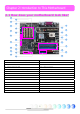
Chapter 2 Introduction to This Motherboard Chapter 2 Introduction to This Motherboard 2.1 How does your motherboard look like? 13 15 14 16 1 17 2 18 19 3 4 20 5 21 6 7 22 23 8 24 25 27 29 9 26 10 11 28 12 30 1. JP28 PS2 KB/Mouse Wakeup Jumper 16. CD-IN Connector 2. AGP 8X Expansion Slot 17. Front Audio Connector 3. 4-pin 12V ATX Power Connector 18. EX_SOUND Connector 4. AGP Protection LED 19. IrDA Connector 5. 478-pin CPU socket supporting Intel P4 CPU 20.
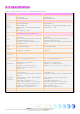
2.2 Specification Here is the main function of your motherboard.
2.
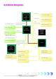
Chapter 3 Hardware Installation Chapter 3 Hardware Installation 3.1 Quick Installation Procedure 12. Installing Drivers & Utilities 1. Installing CPU 11. Installing Operating System (such as, Windows XP) 2. Installing CPU Fan & System Fan 10. Loading Default BIOS, Setting CPU Frequency 3. Installing Memory Module 9. Connecting Back Panel Ports (Keyboard, Mouse, etc) 4. Installing HD, CD-ROM and SATA Disk, etc 8. Installing Other Devices (USB, Front Audio, etc) 5. Connecting ATX Power Cable 7.
3.2 Installation You Have to Know Installing CPU This socket supports FC-PGA2 package CPU, which is the latest CPU package developed by Intel. Other forms of CPU package are impossible to be fitted in. 1. Pull up the CPU socket lever and up to 90-degree angle. 2. Locate Pin 1 in the socket and look for a (golden) cut edge on the CPU upper interface. Match Pin 1 and cut edge. Then insert the CPU into the socket. 3. Press down the CPU socket lever to finish CPU installation.
Installing CPU and System Fans Plug the CPU fan cable to the 3-pin CPUFAN connector. If you have chassis fan, you can also plug it in SYSFAN1 or SYSFAN2 connector. GND +12V SENSOR SYSFAN1 Connector GND +12V SENSOR GND +12V SENSOR CPUFAN Connector SYSFAN2 Connector Note: Some CPU fans do not have sensor pin so that they cannot support fan monitoring.
Installing Memory Modules DIMM slots are designed in Navy Blue and Electronic Blue which are very easy to recognize. Insert the module straight down to the DIMM slot with both hands and press down firmly until the DIMM module is securely in place. Tab Pin 1 Key Note: The tabs of the DIMM slot will clip to hold the DIMM in place when the DIMM touches the slot’s bottom.
Connecting IDE and Floppy Cables Connect the 34-pin floppy cable and 40-pin, 80-wire IDE cable to floppy connector and IDE connector. Be careful of the pin1 orientation. Wrong orientation may cause system damage.
Connecting ATX Power Cables This motherboard comes with a 20-pin and 4-pin ATX power connector as shown below. Make sure you plug them in the right direction. We strongly recommend you to insert the 4-pin connector before connecting the 20-pin connector.
Connecting Front Panel Cable Attach the power LED, speaker and reset switch connectors to the corresponding pins. If you enable “Suspend Mode” item in BIOS Setup, the ACPI & Power LED will keep flashing while the system is in suspend mode. Locate the power switch cable from your ATX housing, which is a 2-pin female connector from the housing front panel. Plug this connector to the soft-power switch connector marked SPWR.
3.3 Other Installation for Your Reference Setting CPU Voltage and Frequency Setting CPU Core Voltage This motherboard supports Voltage ID (VID) function to detect CPU voltage automatically during power-on. However, if users are willing to do overclocking, we also provide a range from 1.10V to 1.85V in the BIOS. Sometimes increasing the original core voltage a little bit will make CPU overclock more properly.
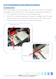
Connecting Serial ATA To connect a serial ATA disk, you have to have a 7-pin serial ATA cable. Connect two ends of the serial ATA cable to the serial ATA header on the motherboard and the disk. Like every other traditional disk, you also have to connect a power cable. Please be noted that it is a jumper free implement; you don’t need to set jumpers to define a master or slave disk.
Adjusting your Hard Disk Setting Except its original 2 sets of parallel IDE, this motherboard supports the latest serial ATA hard disk. If you are unable to find your newly installed serial ATA hard disks on your operating system after having them installed, the problem may lie in the BIOS setting. You can simply adjust BIOS settings to have them work properly. After installing your hard disks properly, you can directly go to BIOS setting screen for adjustment.
If you desire to change the default setting, press Enter for selection list: Disabled: You can choose this item if there are only traditional IDE hard disks had been installed on your system. Disabling this item will also cancel the detection of serial ATA hard disks during POST, which will theoretically speed up your boot-up time a little bit; however, please remember to re-adjust the setting here if you want to use serial ATA hard disk later. Auto: This is factory default setting on this motherboard.
Connecting AGP 8X Expansion Slot AX4SG Max II / AX4SPE Max II provide an AGP 8X slot, a sky blue slot having the latest AGP specification on motherboard. The AGP 8X is a bus interface targeted for high-performance 3D graphic. Traditionally AGP used both rising and falling edge of the 66MHz clock for 4X AGP, and the data transfer rate could achieve 66MHz x 4bytes x 4 = 1056MB/s. Now AGP is moving to AGP 8X mode, which is upgraded to 66MHz x 4bytes x 8 =2.1GB/s.
Connecting IrDA The IrDA connector can be configured to support wireless infrared module, with this module and application software such as Laplink or Windows Direct Cable Connection, user can transfer files to or from laptops, notebooks, PDA devices and printers. This connector supports both HPSIR (115.2Kbps, 2 meters) and ASK-IR (56Kbps). Install an infrared module onto the IrDA connector and enable the infrared function from BIOS Setup, UART Mode, you can use this function.
10/100/1000Mbps LAN Supported On the strength of Gigabit LAN controller on board, this motherboard provides 10/100/1000Mbps Ethernet for office and home use. The Ethernet RJ45 connector is located on the top of USB connectors. The right hand side LED indicates link mode; it lights in orange when linking to network.
Connecting USB2.0 This motherboard provides eight USB 2.0 ports to connect USB devices such as mouse, keyboard, modem, printer, etc. There are four ports on the back panel. You can use proper cables to connect Front USB connector to USB modules or chassis front panel.
Connecting 1394 With IEEE1394 Chip on board (AGERE 1394), having its data transfer rate up to 400Mb/s, this interface can connect to devices that require high data transferring performance such as digital camera, scanner or others IEEE 1394 devices. Please use appropriate cables to connect IEEE1394 devices. Pin1 Pin1 Warning: Please note that Hot-Plug is not allowed on IEEE 1394 headers; doing so will burn the controller IC and damage the motherboard.
Connecting EX_Sound EX_SOUND Connector supports the latest 7.1 Channel and S/PDIF function. S/PDIF (Sony/Philips Digital Interface) is a new audio transfer file format, which provides impressive audio quality through optical fiber and allows you to enjoy digital audio instead of analog audio. Through two specific audio cables, you can connect the EX_SOUND connector to our special EX_SOUND audio module, which bears six ports for S/PDIF and 7.1 Channel. The output and input ports are shown as following.
Connecting SSR_OUT (Surrounding Out) Connector This connector is designed to support 7.1 channels function. Please connect SSR_OUT cable to the Green connector on the EX_SOUND module and this SSR_OUT connector onboard.
Super 7.1 Channel Audio Effect This motherboard comes with an ALC850 CODEC, which supports the latest 7.1 Channel with high quality of audio effects, bringing you a brand new audio experience. To enjoy this function, you have to connect one EX_SOUND Cable and one SSR_OUT cable to our specially designed EX_SOUND module, all of which can be found in accessory. Picture bellow represents the standard location of all speakers in 7.1 Channel sound tracks.
Connecting Front Audio If the housing is designed with an audio port on the front panel, you’ll be able to connect onboard audio to front panel through this connector. By the way, please remove the jumper cap from the Front Audio Connector before you connect the cable. Do not remove this yellow jumper cap if your housing doesn’t have an audio port on the front panel.
Connecting Game Port This motherboard comes with a game port (Joystick-Midi) for you to connect any midi devices or joysticks. To use this function you have to have a joystick module and connect it with a game port cable to this port on the motherboard.
Connecting COM2 (for AX4SG Max II only) This motherboard provides two serial ports. One of them is on back panel connector, and the other is on the upper left of board between PCI slots. With proper cable, you can connect it to the back panel of chassis.
Connecting CD_IN This connector is designed to connect CD Audio cable from CDROM or DVD drive to onboard sound.
Connecting Case Open The “CASE OPEN” header provides chassis intrusion-monitoring function. To make this function work, you have to enable it in the system BIOS, connect this header to a sensor somewhere on the chassis. So, whenever the sensor is triggered by lights or by the opening of the chassis, the system will beep to inform you.
Colored Coded Back Panel (for AX4SG Max II) The onboard I/O devices have PS/2 Keyboard, PS/2 Mouse, RJ-45 LAN Connector, COM1, VGA port, Printer, USB, AC’97 sound and game ports. The view angle of drawing shown here is from the back panel of the housing. PS/2 Mouse Connector SPP/EPP/ECP Parallel Port RJ45 10/100/1000 LAN Jack USB 2.0 Line-In Speaker Out MIC-In PS/2 Keyboard Connector COM 1 Port VGA Port USB 2.0 PS/2 Keyboard: For standard keyboard, which use a PS/2 plug.
Colored Coded Back Panel (for AX4SPE Max II) The onboard I/O devices have PS/2 Keyboard, PS/2 Mouse, RJ-45 LAN Connector, COM1, COM2 port, Printer, USB, AC’97 sound and game ports. The view angle of drawing shown here is from the back panel of the housing. PS/2 Mouse Connector SPP/EPP/ECP Parallel Port RJ45 10/100/1000 LAN Jack USB 2.0 Line-In Speaker Out MIC-In PS/2 Keyboard Connector COM 1 Port COM 2 Port USB 2.0 PS/2 Keyboard: For standard keyboard, which use a PS/2 plug.
LED Indication LED indication including Boot LED, Standby LED and AGP LED are AOpen’s considerate designs that aim at providing you friendly system information. The STBY LED will light up when power is provided to the motherboard, giving you a convenient indication check the system power status in circumstances such as power on/off, stand-by mode and RAM power status during Suspend to RAM mode. BOOT LED will keep blinking when you power the system on and when your system is under POST (Power-On Self Test).
3.4 Jumper Settings Allows you to turn off the voice from buzzer and JP2 Speaker Output speaker. You can choose not to be bothered by the warning made from Dr. Voice when it detects any error in operating system. JP14 Clear CMOS Jumper 1 1 Normal Clear CMOS (default) 1 Buzzer (default) JP2 Speaker Output Jumper 1 Speaker You can clear CMOS to restore system default setting. To clear the CMOS, follow the procedure below. JP14 Clear CMOS Data 1. Turn off the system and unplug the AC power. 2.
JP15/16 Dr. Voice Language Select Dr. Voice provides four language versions: English, German, Japanese and Chinese. You can select your preferred language by JP15 & JP16 jumpers. 1 1 Disable (Default) Enable JP28 KB/Mouse Wakeup Jumper JP15/16 Dr. Voice Languages Select Jumper JP15 JP16 English JP16 JP15 Japanese (Default) Chinese German Pin1 Pin1 JP28 Keyboard / Mouse Wakeup Jumper Pin1 Pin1 This motherboard provides PS2 keyboard / mouse wake-up function.
Chapter 4 Special Features and Utilities Chapter 4 Special Features and Utilities RAID (Redundant Array of Independent Disks) This motherboard supports RAID 0, RAID 1 and RAID 0+1 functions. For more RAID introduction, please visit our website: http://english.aopen.com.tw/tech/techinside/RAID.htm RAID Configuration Utility In order to make sure your system can recognize and operate Serial ATA RAID device smoothly, we have to enter RAID Configuration Utility to do some settings.
Serial ATA RAID for Silicon Image 3114 Silicon Image’s SATARaidTM provides Serial ATA RAID 0 (Striping), RAID 1 (Mirroring) and RAID 0+1 (Striping and Mirroring) functionality to enhance the industry’s leading PCI-to-SATA host controller products. Standard with SATARaid software is a Graphical User Interface (GUI) that provides easy-to-use configurations for different RAID Sets supported. JAVA 2 Runtime Environment Installation The Java 2 Runtime Environment is required for the SATARaid GUI.
Silicon Image SATARaid GUI Overview The SATARaid GUI Installation program configures the SATARaid GUI to automatically start when Windows is started. If the SATARaid GUI does not automatically start or is closed by user, choose the JAVA SATARaid program from Start Menu to launch the GUI.
PBE – Performance Boost Engine Configuring Intel 865 chipset, the performance of this motherboard had been uplifted by implementing PBE Technology (Performance Boosting Engine). Acting as similar as PAT in uplifting the system performance, PBE enables users to optimize the accessing speed and quality between CPU and Memory. Theoretically speaking, CPU must go through some standard paths to access memory. However, with an optimized path created, CPU can access memory through optimized path in a faster way.
SilentTek – Noise is Gone! As CPU clock keeps rocketing higher and higher, it has inevitably brought higher heat and system temperature in a relative way. The way we deal with this heat problem, however, is to spare no effort to add one fan after another to protect our pampered system, expecting these fans cool down our machine as much as they can. But at the same time, we believe that same users are affected terribly by the irritating noises of these fans while working with their PC.
The first image you have here is Voltage Status page. You can find current status of all voltages here and set your expected margins of warning level. You may check your system voltage from the indicating bar here. In “Temp/Fan/Case” page, you can get aware of the current temperature of CPU and the heat inside chassis. Also, you can check if fans are running properly.
The following page is surely the most important part of this utility. You can control the rotation speed of specific fans that you have got the options inside this page. CD-ROM Rotation Speed Control: by enabling the CD-ROM Rotation Speed Control, you can adjust the rotation speed of your CD-ROM. When you set the speed to high level, the CD-ROM will work at its fastest speed and it will run at basic required speed while you set the value to low speed.
Other Useful Features With excellent design ability of R&D team, AOpen boasts for its various powerful and handy features that come with our product like follows. You are welcomed to visit our technical website to learn more about those features. http://english.aopen.com.
Chapter 5 Setting BIOS Chapter 5 Setting BIOS Introduction System parameters can be modified by going into BIOS Setup menu; this menu allows you to configure the system parameters and save the configuration into the 128 bytes CMOS area (normally in the RTC chip or in the main chipset). The Phoenix-Award BIOS™ that installed in the Flash ROM of the motherboard is a custom version of an industry standard BIOS.
How To Use Phoenix-Award™ BIOS Setup Program Generally, you can use arrow keys to highlight items that you want to choose, press key to select, and use and keys to change setting values. You can press key to quit Phoenix-Award™ BIOS setup program. The following table provides details about how to use keyboard in the Phoenix-Award BIOS setup program.
BIOS Upgrade under Windows environment With outstanding R&D ability of AOpen, we now bring you a whole new BIOS Flash wizard ---- EzWinFlash. With an eye to convenience for users, EzWinFlash combines the BIOS binary code and flash module together, so the only thing you have to do is just clicking on the utility you downloaded from web and let it help you complete the flash process automatically.
You may accomplish BIOS upgrade procedure with EzWinFlash according to following steps, and it’s STRONGLY RECOMMENDED to close all applications before you start the upgrades. Download the latest version of BIOS package zip file from AOpen official web site. (Ex: http://english.aopen.com.tw/) Unzip the downloaded BIOS package (ex: WSGMAXII102.ZIP) with WinZip (http://www.winzip.com) in Windows environment. Save the unzipped files into a folder, for example, WSGMAXII102.EXE & WSGMAXII102.BIN.
WinBIOS Utility In the past, users have to keep punching the DEL key during POST (Power-On-Self-Test) screen to get into the BIOS, which is inconvenient and clumsy. From now on, AOpen provides an easier way to configure your BIOS. WinBIOS is a customized utility, running exclusively on AOpen motherboards, to allow you setting up BIOS under Windows environment. Designed to remain traditional-BIOS-alike interface, you can adjust BIOS parameter with clear descriptions for every item.
Function keys: It’s rather easy to handle WinBIOS as if you’re using traditional BIOS setting. Users can use the arrow keys such as to move around items in WinBIOS screen. And use , “+” or “-” to change the setting value. Press to go back to previous screen. Furthermore, the hotkeys shown in the table may help you and save your time. Some settings may not come into effect until you reboot your system. Hotkey F1 F2 F3 F5 F6 F7 F10 F12 Function Description Get help description.
Vivid BIOS technology Have you been fed up with the conservative and immutable POST screen? Let’s rule out the tradition idea that POST screen are stiff and frigid, and let AOpen show you the newly developed VividBIOS to experience the lively vivid colorful POST screen! Unlike earlier graphic POST screen which could occupy the whole screen and mask text information during POST, AOpen VividBIOS deals with graphics and texts separately, and makes them running simultaneously during POST.
Chapter 6 Installing Drivers Chapter 6 Installing Drivers You may think that installing drivers and utilities would be a repeated task of going through those installation wizards and steps-by-steps. Now, you will be surprised with how “Ez” EzInstall could do. Without wizards or steps, all you have to do is to do one click and then it’s done. Click and done. Yes.
6.1 Installing Drivers As you may see from the Installing driver page, EzInstall had picked up necessary for your motherboard. All you have to do is just click on the “GO”, and no more steps afterward, of all listed drivers, grey checks indicate necessary drivers; you cannot click them off. Red checks can be disabled if you don’t want to install them now. Press the icon will prompt the “Install Driver” page. You may also press “Back” to return to the Main page.
6.2 Installing Utilities Installing Utilities is virtually the same as installing drivers. AOpen provides you many friendly and powerful utilities to manage your system. You may find lots of fabulous utilities listed there, and all you have to do is to click on the “GO”, then it will install the utilities to your system right away without complicated steps. Press the icon will prompt the “Install Utilities” page for your selection. You may also press “Back” to get back to the Main page.
Chapter 7 Troubleshooting Chapter 7 Troubleshooting 56
Chapter 8 Technical Support Chapter 8 Technical Support Dear Customer, Thanks for choosing AOpen products. We invite you to register at http://www.aopen.com to become a Gold Member of Club AOpen so as to ensure quality service in the future. In order to maintain the best service to every customer of us, we recommend you to follow the procedures below and seek help from our branches according to the region you buy the product.
Model Name and BIOS Version Model name and BIOS version can be found on upper left corner of first boot screen (POST screen). For example: Phoenix AwardBIOS v6.00PG, An Energy Star Ally Copyright (C) 2003, Phoenix Technologies, LTD. AX4SG Max II R1.02 Mar. 01. 2003 AOpen Inc. AX4SG Max II is model name of motherboard; R1.02 is BIOS version Register Your Motherboard Thanks for choosing AOpen product, please register this motherboard at http://club.aopen.com.