
User Guide


Hardware Installation
2-2
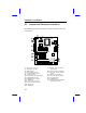
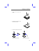
2.2 Jumper and Connector Locations
The following figure shows the locations of the jumpers and connectors on the
system board:
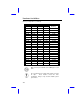
J1: Two-pin fan connector JP3 and JP5: CPU external freq.
J3: ATX power connector select jumper
J4: FDD connector JP4: CPU bus ratio select jumper
J5: Primary IDE connector JP6: Super I/O controller function
J6: Secondary IDE connector jumper
JP13: IrDA connector JP7: Keyboard clock jumper
JP14: Software power switch jumper JP8: P/2 mouse function jumper
JP15: HDD LED connector JP9: Reserved jumper
JP23: Multifunction connector JP10: CMOS jumper
CN1: COM1 port JP11 and JP12: Intel Flash ROM
CN2: PS/2 mouse connector programming jumper
CN3: PS/2 keyboard connector
CN4: Parallel port
CN5: COM2 port