
User Guide


Hardware Installation
2-14
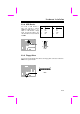
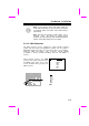
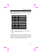
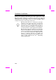
2.3.12 Panel Connector
The Panel (multifunction) connector is a 20-
pin connector marked as PANEL on the
board. Attach the power LED, keylock,
speaker, reset switch, suspend switch, and
green mode LED connectors to the
corresponding pins as shown in the figure.
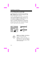
Some housings have a five-pin connector
for the keylock and power LED Since power
LED and keylock are aligned together, you
can still use this kind of connector.
1
+5V
GND
GREEN LED
GND
SUSPEND SW
SUSPEND SW
GND
NC
RESET
GND
11
10 20
GND
KEYLOCK
GND
RESET
POWER LED
SPEAKER
+5V
GND
NC
SPEAKER
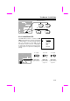
PANEL
1
Speaker
Power LED
Keylock
Reset
Suspend SW
Green LED
11
10
20
+
+
+
+
+
+
PANEL
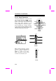
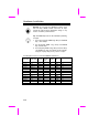
Other housings may have a 12-pin
connector. If your housing has this
type of connector, connect it to
PANEL as shown in the figure.
Make sure that the red wire of the
connector is connected to +5V.
1
+5V
11
10
20
PANEL