
User Guide


Hardware Installation
2-21
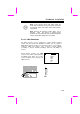
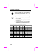
2.5 PCI Slot
PCI Slot 4 and Slot 5 share the
same interrupt INTD.
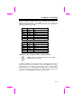
Each PCI slot has four PCI interrupts aligned as listed in the table below. Most
of the PCI cards use only one interrupt at location 1 (pin A6), because the
chipset supports only 4 PCI interrupts. PCI slot 4 and PCI slot 5 share the
same interrupt INTD.
Tip: Since normally PCI VGA does not use interrupt, you
may plug VGA card at either slot 4 or slot 5, and the
other slot can be used for another PCI card.
PCI Slot Location 1
(pin A6)
Location 2
(pin B7)
Location 3
(pin A7)
Location 4
(pin B8)
Slot 1 INTA INTB INTC INTD
Slot 2 INTB INTC INTD INTA
Slot 3 INTC INTD INTA INTB
Slot 4 INTD INTA INTB INTC
Slot 5 INTD INTA INTB INTC
Note: The onboard USB ports share PCI INTD too. If
you enable "USB Host Controller" in BIOS setup, INTD
will be occupied by USB port. That is, PCI slot 4 and slot
5 can only use PCI card that does not need interrupt,
such as VGA.