User Guide for DE45 V2.
Disposal Instruction (US) For better protection of our earth, please don't throw this electronic device into municipal trash bin when discarding. To minimize pollution and ensure utmost protection of the global environment, please recycle the product. For more information about the collection and recycling of Waste Electrical and Electronic Equipment (WEEE), you are invited to visit our homepage at www.aopen.
Verwijderingsinstructie (Dutch) Om mogelijke schade aan het milieu of de menselijke gezondheid door ongecontroleerde afvalverwijdering te voorkomen, moet u dit elektronisch product scheiden van andere soorten afval en op een verantwoorde manier recyclen. Verwijder dit product dan ook alstublieft niet samen met ander huishoudelijk afval. Voor meer informatie over de verzameling en recycling van elektrisch afval en elektronische apparatuur (WEEE), nodigen we u uit om onze homepage te bezoeken www.aopen.
Istruzioni per lo smaltimento (Italian) Per una migliore salvaguardia del nostro pianeta, si prega di non gettare questo dispositivo elettronico nei normali rifiuti al momento dell'eliminazione. Per ridurre al minimo l'inquinamento ed assicurare la massima protezione dell'ambiente, si prega di riciclare il prodotto. Per maggiori informazioni riguardanti la raccolta ed il riciclaggio delle apparecchiature elettriche ed elettroniche residue (WEEE), siete invitati a visitare la nostra homepage www.aopen.
Instrucciones para depositar los productos electrónicos (Spanish) Para proteger mejor el medio ambiente, por favor, no deposite los productos electrónicos en los contenedores de basura tradicionales. Para reducir la contaminación y proteger el medio ambiente se recomienda que los recicle. Para más información acerca de dónde depositar y cómo reciclar Equipos Electrónicos y Desperdicios Electrónicos (WEEE), por favor, visite la página web www.aopen.
Copyright Copyright of this publication belongs to AOpen Inc. AOpen reserves the right to change the content of this publication without obligation to notify any party of such changes or revisions. No part of this publication may be reproduced, transcribed, transmitted, translated into any language, stored in a retrieval system in any form or by any means electronically, mechanically, optically without the prior written permission of this company.
Safety Instructions 1. Please read these safety instructions carefully. 2. Please keep this User’s Manual for later reference. 3. Please disconnect this equipment from connecter before cleaning. Don’t use liquid or prayed detergent for cleaning. Use moisture sheet or cloth for cleaning. 4. Make sure the equipment is connected to the power source with the correct voltage, frequency, and ampere. 5. All cautions and warnings on the equipment should be noted. 6.
FCC notice This device has been tested and found to comply with the limits for a Class B digital device pursuant to Part 15 of the FCC Rules. These limits are designed to provide reasonable protection against harmful interference in a residential installation. This device generates, uses, and can radiate radio frequency energy and, if not installed and used in accordance with the instructions, may cause harmful interference to radio communications.
Notice: Peripheral devices Only peripherals (input/output devices, terminals, printers, etc.) certified to comply with Class B limits may be attached to this equipment. Operation with non-certified peripherals is likely to result in interference to radio and TV reception. Caution Changes or modifications not expressly approved by the manufacturer could void the user’s authority, which is granted by the Federal Communications Commission, to operate this computer.
1
Index 1. Outlook …………..……………………………………………2 2. Product Specification….…………………………...………...4 3. Internal Connectors ………..…………………………………5 4. Packing List……………………………………………………6 5. Chassis and Holder Dimension ……………………………..7 6. Appendix 1 Assembly Guide…..………..………….……….15 7. Appendix 2 Table of Screw and Torque………….………...
1.
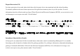
Rear IO Kensington lock hole DC20V/12V HDMI VGA2 LAN VGA1 Antenna hole COM port USB 2.
2. Product Specification CPU Socket P Support Intel Core 2 Duo and Celeron CPU, FSB 667/800/1066 MHz Chipset Intel GM45 + ICH9M Chipset Memory Dual Channel Mode, SO-DIMM DDRII x 2, DDRII 667/800 Max memory size : 4GB Graphics Integrated VGA Engine in GM45 chipset (Intel GMA X4500MHD) Expansion mini Card Slot x 1 Slot Audio Realtek HD AUDIO CODEC ALC662 LAN Integrated Intel 10/100/1000 Mbps LAN Controller Front Panel IO Power Button x 1, HDD/Power indicator (Blue) x 1, USB 2.
3.
4.
5. Chassis and Holder Dimension A.
B. LH01 L type Holder(Include 2 piece holder and 8 FPH M3 screws) B-1 L type Holder is a versatile holder, you can screw it on any place you want. B-2 You can put on the L type Holder on 2 sides, and screw it tightly.
B-3 Dimension of L type Holder.
C.VM02 Monitor Holder (Include 2 piece holder and 4 FPH M3 and 4 FPH M4 screws) C-1 Monitor Holder is base on VESA standard (10cm/7.5cm interval) for you to screw the Digital Engine behind the monitor. You can put on the Holder on monitor VESA mounting hole first, and screw it tightly, then put Digital Engine on VM02 holder and use 4 M3 screws to fix it.
C-2 Dimension of VM02 Monitor Holder (unit: mm) 11
D. ST01 Vertical Holder (Include 2 piece holder and 8 FPH M3 screws) D-1 You can put the Digital Engine Vertical with the holder D-2 You can put the stand(s) on right side, and screw it tightly.
D-3 Dimension of ST01 Vertical Holder.
D-4 Dimension of ST01 Vertical Holder.
6. Appendix 1 Assembly Guide 1. Open Housing 1-1. Detach 2 pcs of the rear side screw ( FPH M3 screw ) by the electric screw driver . (Screwdriver torque : 5.0±0.2 kgf. cm ) 1-2. Push the Upper case to remove it .
1-3. Detach 4 pcs of the supporter screw ( FPH M3 screw )by the electric screw driver (Screwdriver torque : 5.0 ±0.2 kgf. cm ) 16 1-4.
1-5.
2. Install Key components 2-1 Install Memory 2-1-1. Insert the memory on the socket as this angle.
2-1-2. Then press the DIMM as flat on the Motherboard, and you will hear the click voice.
2-1-3.Unscrew the CPU cooler 2-1-5. Unscrew CPU socket Counterclockwise direction Unscrew 2-1-4.
2-1-6 Put the CPU into the socket, and check the direction. 2-1-8. Put on the cooler and screw it tightly . clockwise direction 2-1-7. Screw the CPU socket.
2-2 Install HDD on Supporter without ODD 2-2-1 Install Card Holder Put the Card Holder on the supporter, and screw it with 1pcs of M2 screw. (Screwdriver torque : 0.7±0.1kgf.cm) 2-2-2.Insert the MPI-SATA card into HDD Screw internal card to Card holder with 2pcs of M2 screws.(Screwdriver torque:0.7±0.1kgf.
2-2-3. Put the HDD on support Please pay attention to the direction of SATA HDD 2-2-4. and screw HDD with 4pcs of FPH M3 screw (on both flanks) (Screwdriver torque : 2.5 ±0.1 kgf.
2-3 Install HDD on Supporter with slim ODD 2-3-1 Put slim ODD on the top side of supporter, screw the position 1 and 2 with M2 screw first, then screw position 3 and with M2 screw to fix the slim ODD. (Screwdriver torque : 0.7±0.1kgf.
2-3-2.Insert the MPI-SATA card into HDD 2-3-3 Screw MPI-SATA card to ODD with 2 pcs of M2 screws. (Screwdriver torque : 0.7±0.1kgf.cm) 2-3-4. Put the HDD on support Please pay attention to the direction of SATA HDD and screw HDD with 4pcs of FPH M3 screw (on both flanks) (Screwdriver torque : 2.5 ±0.1 kgf.
FPH M2xL3 Screw 2-3-5 FPH M3xL5 Screw 26
3. Assemble the Supporter & Upper Case 3-1.
3-2. Install the supporter (Only HDD is on the supporter now) 3-2-1. Make sure the MPI-SATA card is correctly insert into the socket 3-2-2.Screw 4pcs of M3 screw at the supporter. (Screwdriver torque : 5.0 ± 0.2 kgf.
3-3. Install the supporter (HDD and ODD are on the supporter now) 3-3-1. Make sure the MPI-SATA card is correctly insert into the socket 3-3-2.Screw 4pcs of M3 screw at the supporter. (Screwdriver torque : 5.0 ± 0.2 kgf.
3-4. Assemble the upper case (without ODD) 3-4-1. Connect the power switch wire. 3-4-2. Connect the Front-USB wire to upper-case. 2 1 3-4-3. Adjust the USB cable to arrange the cable under the supporter . Accord the photo.
3-5 Assemble the upper case (with ODD) 3-5-1. Remove ODD door on upper case 3-5-2. Connect the power switch wire. 3-5-3.. Accord the photo Connect the Front-USB wire to upper-case 3-5-4. Adjust the USB cable to arrange the cable under the supporter.
3-6.Screw the upper case 1. 3. Screw 2pcs of M3 screw at rear side (Screwdriver torque : 5.0 ±0.2 kgf. cm ) 2.
Without slim ODD With slim ODD 33
3-7 Assemble Module of Wireless LAN Mini Card or TV Tuner Mini Card 3-7-1. cable and nut A,B inside housing; C,D outside housing A B C 3-7-2. Note the hole shape to adjust the antenna SMA connector to insert into the hole. D 3-7-3. Insert a washer to one end of the antenna wire . Attaching another washer and nut to the antenna wire . 3-7-4. Use the screwdriver or the long nose pliers to fix the nut . . (Screwdriver torque : 1.5 ±0.1 kgf.
3-7-5. Detach screw and align the notch to 3-7-6. Install the antenna wire with the button Insert mini card into the slot and fix with screw. of the wireless LAN or TV-tuner Mini card . 3-7-7. Arrange the wire to avoid damaging the wire. According the photo. 3-7-8. Caution: Arrange the wire or cable not well. The MPI–SATA card will damage the wire or cable .
7. Appendix 2 Table of Screw and Torque No. Screw Photo Position Q’ty Screw spec. Torque Screw driver spec. 1 Rear side 2 FPH M3- L5 5±0. 2 kgf-cm ♁ Phillips #2 2 HDD 4 FPH M3- L5 2.5±0. 2 kgf-cm ♁ Phillips #2 Length ≧ 8cm 3 Supporter 4 FPH M3- L5 5±0. 2 kgf-cm ♁ Phillips #2 4 MPI-SATA card 2 FPH M2- L3 0.7±0. 1 kgf-cm ♁ Phillips #1 5 Slim ODD 4 FPH M2- L3 0.7±0.
37
P/N:49.ADE01.