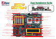
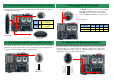
PS/2 Mouse Connector SPP/EPP/ECP Parallel Port Speaker Out RJ45 10/100 LAN Jack (Optional) FAN3 Connector PS/2 Keyboard USB Port Connector COM 2 Port COM 1 Port Line-In MIC-In AUX-IN Connector CD-IN Connector FAN2 Connector Intel 82550 10/100 LAN Controller 1500μF Low ESR Capacitors CPU1 FAN connector CPU2 FAN Connector AGP Pro Slot USB Connector Dual CPU sockets CPU #2 CPU #1 FAN1 Connector 32 Bit PCI Slot x 5 4Mbit Flash BIOS Game Port Connector ATX 20-pin Power Connector AGP Pro Power Conn
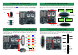
1. JP14 Clear CMOS You can clear CMOS to restore system default setting. To clear the CMOS, follow the procedure below. 1. Turn off the system and unplug the AC power. Everything you need to boot this motherboard is included in this Easy Installation Guide. For more information, a complete Online User's Manual can be found in the Bonus Pack CD Disc. Thanks for the help of saving our earth. 2. Remove ATX power cable from connector PWR2. 3. Locate JP14 and short pins 2-3 for a few seconds. 4.
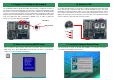
. Installing Processor 5. Setting CPU Voltage & Frequency 1. Pull up the CPU socket level and up to 90-degree angle. Setting CPU Core Voltage This motherboard supports CPU VID function. The CPU core voltage will be automatically detected and the range is from 1.05V to 1.825V. It is not necessary to set CPU Core Voltage 2. Locate Pin 1 in the socket and look for a (golden) cut edge on the CPU upper interface. Match Pin 1 and cut edge. Then insert the CPU into the socket. CPU socket lever 3.
6. Support Four USB Connectors 8. Connecting IDE and Floppy Cables This motherboard provides four USB connectors to connect USB devices, such as mouse, keyboard, modem, printer, etc. There are two connectors on the PC99 back panel. You can use proper cable to connect other USB connectors to the back panel or front panel of chassis. Connect 34-pin floppy cable and 40-pin, 80-wire IDE cable to floppy connector FDC and IDE connector. Be careful of the pin1 orientation.
12. Connecting CD / AUX Connector 10. Connecting 68-pin Ultra 160 SCSI Cable (DX37 Plus-U only) The DX37Plus-U provides two 68-pin Ultra Wide/Ultra 2/3 SCSI connectors for 16-bit or 16-bit differential SCSI devices. The AUX-IN connector is used to connect MPEG Audio cable from MPEG card to onboard sound. CD-IN (Black) The CD-IN connector is used to connect CD Audio cable from CDROM or DVD drive to onboard sound.
16. Wake On LAN 14. Support 10/100 Mbps LAN onboard The South Bridge V8233 of VIA Apollo Pro266T chipset includes a fast Ethernet controller on chip. On the strength of Intel 82550 PHY on board, which is a highly-integrated Platform LAN Connect device, it provides 10/100M bps Ethernet for office and home use, the Ethernet RJ45 connector is located on the back panel. The green LED indicates the link mode, it lights when linking to network and blinking when transferring data.
Part Number and Serial Number If you encounter any trouble to boot you system, follow the procedures accordingly to resolve the problem. The Part Number and Serial number are printed on bar code label. You can find this bar code label on the outside packing, on ISA/CPU slot or on component side of PCB. For example: Start Turn off the power and unplug the AC power cable, then remove all of the addon cards and cables, including VGA, IDE, FDD, COM1, COM2 and Printer. Part No. Serial No.
1 Online Manual: Please check the manual carefully and make sure the jumper settings and installation procedure are correct. http://www.aopen.com/tech/download/manual/default.htm Dear Customer, 2 Thanks for choosing AOpen products. To provide the best and fastest service to our customer is our first priority. However, we receive numerous emails and phone-calls worldwide everyday, it is very hard for us to serve everyone on time.