Chapter 0 Catalogue Chapter 0 Catalogue ........................................................0-1 Chapter 1 How To Use This Manual .......................1-1 1.1 A Thank-you Note Before You Get Started ......................................................................... 1-1 1.2 The Features Of This Manual ............................................................................................. 1-2 1.3 Preliminary Tools ..............................................................................
Chapter 3 Check What You've Achieved ..3-1 3.1 Connect The External Peripherals ...................................................................................... 3-1 3.2 Turn On The Power To Check............................................................................................. 3-5 3.3 Postscripts ..........................................................................................................................
Chapter 1 How To Use This Manual 1.1 A Thank-you Note Before You Get Started First of all, we would like to express our gratitude to your purchase of this specially-designed bare-system by AOpen. Once again, this bare-system is designed uniquely to meet all your personal needs with our great industrial designing ability and our everlasting perseverance with the quality of all products. This manual is for those who want to set up the computer by themselves.
1.2 The Features Of This Manual In this manual, you will be able to know how to: Set up a personal computer on your own. Correctly and safely put everything together and get some ideas about hardware. Make the setup easier with some practical techniques. In addition, this manual DOES NOT offer you: Any sorts of back doors, such as overclocking. A great bunch of hardware standard that is difficult to understand. Lengthy, fanciful but vague theories.
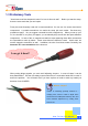
1.3 Preliminary Tools "A workman must first sharpen his tools if he is to do his work well". Before you start the setup, there are some tools that you can't spare. Firstly, the most frequently used tool is cross screwdriver. You can use it to screw most interior components. A suitable screwdriver can make the setup job much easier. screwdriver apply? No, we suggest a screwdriver with a magnetic tip.
[Note] 1-4 How To Use This Manual
Chapter 2 Start To Assemble 2.1 Open The Housing This product you bought from AOpen Baresystem series belongs to special standards of MicroATX / ATX. And this bare-system has following distinguishing features: The MicroATX/ATX housing provides you a big space to expand capacity. Bend-in edges ensure your safety when assembling. A highly efficient 300/250W power supplier ensures your computer work smoothly in most cases. FCC Class B / DoC and CE conformed standards guarantee your health.
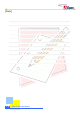
Remove both sides of housings. To remove side housings, slide the housing a bit backward and lift it up. Procedure goes the same with the other side.. Then you can have a clear look of AOpen Baresystem.
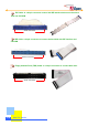
2.2 Check Accessories Opening the housing, you are supposed to see the following accessories: Power cord: Connects the computer power. Are power cords all the same? Power cords are various in different countries. Please use an appropriate power cord according to your country. Fixed screws: After opening the accessory parcel, you'll see three different types of screws as follows: As shown in the picture, the threads on NO.1 screw are wide and it is a so-called hex screw. As shown in the picture, the NO.
IDE Cable: is a 40-pin connector used to link IDE interface devices such as hard disk and CD-ROM. 40-Pin Connector IDE Cable: a 80-pin connector to connect the hard disk with IDE interface and CD-ROM. 80-Pin Connector Floppy diskette Drive (FDD) Cable: is a 34-pin connector to connect disk drive.
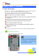
2.3 Check Your I/O Back-panel HQ / LX /HX series Baresystem is equipped with an all-purpose I/O back-panel. You can break through the port bracket according to your personal needs. If your motherboard has built-in sound effects or network functions, then you need more ports to connect external speakers and network. Check I/O connector ports on the motherboard with your housing and decide which port brackets you need to break through.
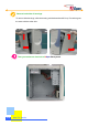
Use a tool to break the iron bracket on the I/O back-panel. As shown in the picture, use a tool to tear down the bracket by twisting it several times. Be careful when twisting!! When breaking brackets, it is wise to use a pliers to avoid cutting yourself. If you fail to have a pliers on hand, pad a piece of cloth on your palm to tear it down.
2.4 Set Up Hard Disk A Hard disk is the place where most of the data is stored. Therefore, it is one of the most important components in a personal computer. This section will introduce you the knowledge of the hard disk and some important tips when you set it up. Get to know the hard disk Taking out the hard disk from the parcel, you will see the following equipment: Jumper configurations Adjust Jumpers on your hard disk As has been mentioned to you, we assume you know the definition of Jumpers.
Place the hard disk into the frame. Tighten the screws to the frame. In fact, a hard disk is a very fragile and delicate device though it is covered with a metal housing. When in operation, a slight vibration might do great harm. screw it on the frame securely. Therefore, be sure to Don't mess up screws!! Generally there are special screws for a hard disk in the parcel when you buy a new hard disk. If no screws are attached, use those packed in the accessory parcel. Make sure to use the NO.2 screws.
2.5 Set Up Motherboard It is very easy to set up a motherboard in AOpen Baresystem. Just place the motherboard in the correct position and tighten the screws. Please follow the steps below: Read the handbook of the motherboard and adjust Jumper settings. Currently almost all motherboards have a Jumper-free design (or Jumperless design). Even so, there are still some other functions that need to be adjusted through Jumpers.
How many brass studs should I screw? There are holes for screws on the motherboard. Just compare the position of the holes with the iron base of the housing. Then you will know the position where to screw the brass studs. The number of the brass studs depends on the motherboard you purchased. With an angle of 45 degrees, level the motherboard at the back panel brackets and place it on the brass studs you just screwed. Tighten the screws respectively with screws NO.
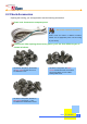
2.6 Set Up CPU When setting up CPU, please don't go wrong with the direction of CPU. distinguish its direction. First of all, let's have a look at what CPU is like: It is very easy to Note that the arrow indicates the first pin As shown in the picture, it's FC-PGA CPU of Intel Pentium III, which is so-called Socket370 CPU. There are still many other varieties of CPU available in the marketplace. attention to the model when you are purchasing. Please pay It should be consistent with your motherboard.
Aim the arrow marked on CPU at the first pin position on the socket. Don’t worry!! CPU socket also has a foolproof device. You may find out the pin arrangement at four corners of CPU is different. Two of them have a bevel-angle, which is a foolproof. As long as you don't insert it too hard, the CPU is unable to be located into the socket if it is wrongly placed! After CPU is located in the socket, pull down the lever and click to the tenon.
Set up the cooling fan above the CPU socket. Get the clip of the cooling fan hooked by the tenon above the socket. Be careful not to scratch the motherboard! When setting up the cooling fan, please avoid the clip scratching the motherboard; otherwise it may cause serious damage! Use a tool to place the clip at the other side into the tenon. Lastly, plug in the fan connector. Be aware of its direction.
Set Up Pentium 4 CPU With the increasing popularity of Pentium4 CPU in the market, we considerately introduce CPU installation of Pentium4 in this section. As with setting up all types of CPU, please don't go wrong with the direction, let’s take a look at Pentium4 CPU itself. Note that the arrow indicates the first pin As shown in the picture, it's a Micro FC-PGA CPU of Intel Pentium4, which is the so-called Socket478 CPU. Please pay attention to the model when you buy one.
Aim the arrow mark on CPU at the first pin in the socket Don’t worry!! CPU socket also has a foolproof device. You may find the pin arrangement at four corners of CPU is different. Two of them have a bevel-angle, which is for foolproof purpose. As long as you don't insert it too hard, the CPU is unable to be located into the socket if it is wrongly placed! After CPU is located in the socket, pull down the rod and click to the tenon.
Set up the cooling fan above the CPU socket Motherboard for Pentium4 CPU usually comes with a special-designed retention module which is as shown below. Be careful not to scratch the motherboard! When setting up the cooling fan, please avoid the iron piece scratching the motherboard; otherwise it may cause serious damage! Press iron sticks to get hooked on the retention module. At last, plug in the fan connector. Be aware of its direction.
Connect ATX power cord to the motherboard Before connecting 20-pin ATX power connector to transmit the current of the power supplier to the motherboard, please remember to plug in the 4-pin power connector at the first place. Still pay attention to the direction when you plug it in.
2.7 Plug In Memory The DIMM modules available on the market belong to several standard modules. The pictures shown below are the most common use ones. As the pictures show below, the jag is the foolproof device. Be careful not to plug in the wrong side. This one is a 168-pin SDRAM. Pay attention to the direction of the jag. This one is a 184-pin DDR SDRAM. Pay attention to the direction of the jag. Pull open two sides of tenons on the memory socket.
Aim the first pin and the jag on the memory module at the marked area of the socket. Insert the memory module vertically downward into the socket with both hands. Please be careful when you insert the memory module.
2.8 Set Up Front USB / Audio Module (Optional) Except standard audio output and USB connectors, AOpen also considerately designs "the front audio module (Optional equipment)" for you. It allows you to conveniently connect speakers and earphones on the front panel and there are two sets of USB jacks to make your system a greater extensibility.
Screw the front-panel audio connector module to the housing Connect the signal cable to the motherboard Please see the manual of your motherboard for the precise position of USB connector and front audio module. Then, connect the USB signal cable and audio signal cable from the front audio module. All of the connectors and cables have a foolproof device. You won’t go wrong. Do all USB face the same direction? The pin direction of the USB may be different on various motherboards.
2.9 Set Up Floppy Diskette Drive The diskette drives available on the market are 3.5-inch with the capacity of 1.44MB. The floppy cable applied here is different from the IDE device introduced in the previous section. It uses a narrow 34-pin cable and no Jumper has to be adjusted before the diskette drive is installed. Know your diskette drive. This is where the first pin is located Connector of diskette cable Remove the diskette drive cover on the front panel of housing.
Place the diskette drive into the housing. Tighten the screws. Here we use NO.3 screws.
2.10 Set Up Optical Storage Devices Basically speaking, the set-up procedure of IDE CD-ROM drive is almost the same as that of installing IDE hard disk. First of all, let's take a look at your CD-ROM drive: CD audio Jumper settings Power connector IDE cable connector Adjust the Jumper settings of CD-ROM drive. Like hard disk drive, every IDE device has to adjust Jumper settings. Here we set CD-ROM drive as Slave. Set CD-ROM drive to Slave as marked.
Plug in audio cable The audio cable is a small cable composed of red, black and white lines. The red line is used to connect the right volume channel while the white one is used to connect the left volume channel. And the black line is used as earthing. As a result, when connecting the audio cable to CD-ROM drive, plug the red line to the side marked "R" and the white line to the side marked "L".
Place CD-ROM drive into the housing. Screw the CD-ROM drive with NO.3 screws. Next, lock the CD-ROM drive in the fixed frame. The screws used for CD-ROM drive are the same as those used for diskette drive. They are NO.3 screws with narrow threads.
2.11 Connect Signal Cable After setting up disk devices, we need to connect their cables to the motherboard. As a result of various connector locations on different motherboards, it is wise to read the words marked on the motherboard before you connect the cable. connectors are marked on the motherboard. Let's take a look at how these You won't go wrong if you read the words correctly.
Connect the cable of CD-ROM drive to the motherboard. Aim the red side of cable at the first pin Connect the cable of hard disk drive to the motherboard. Where is Pin1? When connecting IDE cables, bear in mind to aim the red side of IDE cables at the first pin of What if there is no foolproof device on the cable? If you happen to have a no fool-proof cable, just remember that the first pin is next to the red line and it would be safe to locate the first pin close to the power cord.
Connect CD audio cable to the motherboard We have connected one side of cable to the CD-ROM drive earlier, now we are going to connect the other end to work it. Please note that the position of CD audio connectors is various on different motherboards. know how to read the words on the motherboard. You will never go wrong if you You won't go wrong if you can recognize the word on the motherboard. Keep in mind that the red line is aimed at the right volume channel marked as "R".
2.12 Connect Power Cord There is nothing easier than connecting power cord. Both power cord connector and socket have a foolproof device. You cannot plug it in if you get it in the wrong direction. Just match the connector bevel with that of the socket to plug it in. Connect the power cord of hard disk drive. Let's have a look how the power connector is like: You won’t go wrong if you match the bevel of connector. Both power cord connector and socket have a foolproof device.
Connect the power cord of CD-ROM drive. Then connect the power cord of CD-ROM. Both power cord connector and socket have a foolproof device. You cannot plug it in if you get it in the wrong direction. Connect the power cord of the floppy diskette drive. The power cord shown below is for the floppy diskette drive. Although powered by 12V as well, you can easily recognize it with a smaller connector. Pay attention to the shape and direction of the connector.
Connect ATX power cord to the motherboard. Finally comes the one marked P1. This ATX power connector transmits the current of the power supplier to the motherboard. plug it in. Please pay attention to the direction when you Be careful the direction of clip when plugging. Pentium 4 CPU power connector (Only For Pentium 4 CPU users) If you choose a P4 motherboard you have to connect a special connector as shown below. Just connect it with a rectangle female connector on the motherboard.
2.13 Connect The Front Panel LEDs The front panel LEDs indicate the current situation of the system such as power-indicating light, hard disk reading indicator, ATX power switch and system Reset button. their pin locations on the motherboard: Now look at Pins to connect the front panel LEDs. Due to the lack of the standard pin module on the front panel lights, please refer to your motherboard manual and follow its instructions to connect each signal cable.
2.14 Set Up Interface Card If there is no built-in VGA card in your system, you have to choose a suitable one. Read this section carefully if you desire to install other interfaces (such as network card, modem card, image card, or 3D-acceleration card). We take VGA card as an example to demonstrate how to set up an interface card. similar.
Take apart the rear port bracket that you need to install on the housing. You should remove the brackets before setting up the interfaces in order to lock them in. It is very easy to remove the rear port brackets from the housing. You can use a screwdriver to help you to remove our specially designed rear port brackets. Aim the golden finger of the interface card at the socket you want to connect, and insert the interface card vertically downward into the socket with both hands.
Screw the interface card to the housing with NO.1 screws.
2.15 All Set So far we had almost completed all the assembling. It is much easier than you imagine, isn't it? The final thing to do is to put both sides of housings back. Then it is all done! Relocate both sides of the housing. Please note that you have to locate the hooks of the side housing into the holes on the frame to cover it securely. Tighten screws.
[Note] 2-38 Start To Handle
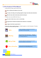
Chapter 3 Check What You've Achieved 3.1 Connect The External Peripherals Having spent so much effort, do you feel confident to DIY your computer? Now, let's take a look at the connectors at the back of your system and know their names, purposes and positions.
Connect keyboard and mouse Connect monitor and tighten screws Connect the D Type 15-pin plug of the monitor cable to the monitor connector at the back of bare-system and tighten the screws. If the module you choose doesn’t have a VGA function, please note that the connector position is different. Remember to tighten screws after connecting.
Connect the multimedia speaker Connect the jacks of the multimedia speakers as marked. The device conformed to PC99 standard has been marked by certain colors. You won't get wrong if you follow those marked colors. Connect network cable If the model you choose has a built-in network function on the motherboard or you have installed a Network Interface card, please remember to connect RJ-45 network cable.
Connect telephone cable You can install an internal modem card to allow your computer linking with the colorful Internet cyber world via a phone line. Please beware that there are two connectors on the modem card. One connects to phone line (To Line) while the other one connects to telephone (To Phone). To Line To Phone Finally connect the power supply cable. Please adjust the voltage setting according to your local standard.
3.2 Turn On The Power To Check Ok, all cables have been properly connected. computer? Are you getting confident of assembling a The final step is to turn on the power to check what you have done so far. Now you can take a short break and have a drink before turning on the computer to see how things are going.
After pressing Delete, you'll see the following BIOS setup: Now, you can move the cursor by using direction keys on the keyboard.
Then, the following dialogue screen will pop up to confirm the default BIOS values. Please press "Y" to confirm and then press Enter. Finally, move the cursor to "Save & Exit Setup" and press Enter to save the parameters and exit BIOS setup.
At the same time, type "Y" in the dialogue box and press Enter to exit.
3.3 Postscripts First of all we would like to congratulate your successful computer DIY. Now you can install an operation system and some application software according to your personal requirements. However, these are beyond discussions of this manual whose main aim is to teach you correct understanding of DIY skills and enable you to assemble a computer step by step. As for the application part, you can find all varieties of books with comprehensive introduction in bookstores.
[Note] 3-10 Check What You've Achieved