MK89-N / MK89-L / MK89-1394 Online Manual MK89-N / MK89-L / MK89-1394 DOC. NO.
MK89-N / MK89-L / MK89-1394 Online Manual W h a t ’s i n t h i s m a n u a l MK89-N / MK89-L / MK89-1394 ............................................................................................................ 1 What’s in this manual ...................................................................................................................................................... 2 You Must Notice .......................................................................................................
MK89-N / MK89-L / MK89-1394 Online Manual ATX Power Connector ................................................................................................................................................... 30 AC Power Auto Recovery .............................................................................................................................................. 30 IDE and Floppy Connector .......................................................................................................
MK89-N / MK89-L / MK89-1394 Online Manual JP14 Clear CMOS Data ................................................................................................................................................ 49 JP28 Keyboard/Mouse Wakeup Jumper........................................................................................................................ 50 Battery-less and Long Life Design ............................................................................................................
MK89-N / MK89-L / MK89-1394 Online Manual Glossary ....................................................................................................................................... 87 AC97 CODEC ............................................................................................................................................................... 87 ACPI (Advanced Configuration & Power Interface) ..................................................................................................
MK89-N / MK89-L / MK89-1394 Online Manual Hyper Threading ........................................................................................................................................................... 92 IEEE 1394 ..................................................................................................................................................................... 93 Parity Bit .......................................................................................................
MK89-N / MK89-L / MK89-1394 Online Manual Technical Support ..................................................................................................................... 102 Product Registration ................................................................................................................. 105 How to Contact Us ....................................................................................................................
MK89-N / MK89-L / MK89-1394 Online Manual You Must Notice Adobe, the Adobe logo, Acrobat is trademarks of Adobe Systems Incorporated. AMD, the AMD logo, Athlon and Duron are trademarks of Advanced Micro Devices, Inc. Intel, the Intel logo, Intel Celeron, Pentium II, Pentium III, Pentium 4 are trademarks of Intel Corporation. Microsoft, Windows, and Windows logo are either registered trademarks or trademarks of Microsoft Corporation in the United States and/or other countries.
MK89-N / MK89-L / MK89-1394 Online Manual Before You Start This Online Manual will introduce to the user how this product is installed. All useful information will be described in later chapters. Please keep this manual carefully for future upgrades or system configuration changes. This Online Manual is saved in PDF format, we recommend using Adobe Acrobat Reader 4.0 for online viewing, it is included in Bonus CD disc or you can get free download from Adobe web site.
MK89-N / MK89-L / MK89-1394 Online Manual Ov er vi e w Thank you for choosing AOpen MK89-N / MK89-L / MK89-1394. The MK89-N / MK89-L / MK89-1394 is based on AMD® K8 Socket 754 motherboard with micro ATX form factor featuring the AMD K8 CPU. As high performance chipset built in the M/B, MK89-N / MK89-L / MK89-1394 support AMD® K8 Socket 754 series Nvidia NForce3 processor and 200MHz system clock. In the AGP performance, it has one AGP slot and supports AGP 8X mode for you to insert 1.5V AGP card.
MK89-N / MK89-L / MK89-1394 Online Manual MK89-N / MK89-L / MK89-1394 Comparison Table Following we list the different functions in those four models. “V” represents those functions that the model equips with and “X” represents functions that model doesn’t have. Please always refer to this page to see the functions of your model.
MK89-N / MK89-L / MK89-1394 Online Manual F e a t u r e Hi g h l i g h t CPU Supports AMD® Socket 754 series CPU with 200MHz system clock designed for Socket 754 technology. Chipset The NVIDIA ® nForce3 processor is a single-chip, highly integrated, high-performance, low-cost PC2001-compliant peripheral controller with AGP 8X and an AMD K8 CPU interface. The nForce3 implements a fast dedicated HyperTransport link, running at up to 3600MB/s, to communicate with the AMD K8 CPU.
MK89-N / MK89-L / MK89-1394 Online Manual Memory MK89-N / MK89-L / MK89-1394 supports Double-Data-Rate (DDR) RAM. The DDR RAM interface allows zero wait state bursting between the SDRAM and the data buffers at 333/266/200MHz. The two slots of DDR RAM can be composed of an arbitrary mixture of 64, 128, 256, 512MB or 1GB DDR RAM and maximum up to 2GB. The MK89-N / MK89-L / MK89-1394 allows DDR RAM to run at either synchronous or pseudo-synchronous mode with the host CPU bus frequency (400/333/266MHz).
MK89-N / MK89-L / MK89-1394 Online Manual S/PDIF Connector S/PDIF (Sony/Philips Digital Interface) is the newest audio transfer file format, which provides impressive quality through optical fiber and allows you to enjoy digital audio instead of analog audio. Power Management/Plug and Play Supports the power management function that confirms to the power-saving standards of the U.S. Environmental Protection Agency (EPA) Energy Star program.
MK89-N / MK89-L / MK89-1394 Online Manual Enhanced ACPI Fully implement the ACPI standard for Windows ® 95/98/ME/NT/2000/XP series compatibility, and supports Soft-Off, STR (Suspend to RAM, S3), STD (Suspend to Disk, S4) features. Super Multi-I/O Provides one high-speed UART compatible serial port and one parallel port with EPP and ECP capabilities.
MK89-N / MK89-L / MK89-1394 Online Manual Q ui c k I n s t a l l a t i o n P r o c e d ur e This page gives you a quick procedure on how to install your system. Follow each step accordingly. 1. Installing CPU and Fan 2. Installing System Memory (DIMM) 3. Connecting Front Panel Cable 4. Connecting IDE and Floppy Cable 5. Connecting ATX Power Cable 6. Connecting Back Panel Cable 7. Power-on and Load BIOS Setup Default 8. Setting CPU Frequency 9. Reboot 10.
MK89-N / MK89-L / MK89-1394 SYSFAN2 Connector Front Audio Connector CD-IN Connector Online Manual M o t h er b o ar d M a p AUX-IN Connector Colored Back Panel JP28 KB/Mouse Wakeup Jumper Resetable Fuse 184-pin DIMMx2 supports DDR400/333/266(Max.
MK89-N / MK89-L / MK89-1394 Online Manual Bl o c k D i a g r a m DDR400/333/266 Up to 2GB PCI Bus DDR SDRAM Socket x2 32-bit PCI Slot x3 200MHz System Bus Socket 754 AMD K8 CPU ATA 66/100/133 Primary Channel Secondary Channel Nvidia nForce3 Audio CODEC AGP 8X Slot IDE Drive x4 AC’97 Link Modem CODEC AGP Bus 2Mb Flash EEPROM Parallel Port RealTek LAN LAN connect Component Serial Port x1 IEEE 1394 x2 1st USB Port 2nd USB Port 3rd USB Port USB2.
MK89-N / MK89-L / MK89-1394 Online Manual Har dwar e Ins tal l ati o n This chapter describes jumpers, connectors and hardware devices of this motherboard. Note: Electrostatic discharge (ESD) can damage your processor, disk drives, expansion boards, and other components. Always observe the following precautions before you install a system component. 1. Do not remove a component from its protective packaging until you are ready to install it. 2.
MK89-N / MK89-L / MK89-1394 Online Manual A b o u t “ M a n u f a c t ur e r U p gr a d e O p t i o n a l ” a n d “ Us e r U p g r a d e O pt i o n a l ” … When you read this online manual and start to assemble your computer system, you may find some of functions are called “Manufacturer Upgrade Optional”, and some are called “User Upgrade Optional”. Though all AOpen motherboards include many amazing and powerful features, in some situations, these powerful features are not used to every user.
MK89-N / MK89-L / MK89-1394 Online Manual C P U I n s t al l a ti o n This motherboard supports AMD® Socket 754 series CPU. Be careful of CPU orientation when you plug it into CPU socket (with CPU Overheat Protection function implemented, the system will be automatically powered off when CPU temperature reaches 97 degree). 2. Locate Pin 1 in the socket and look for a black dot or cut edge on the CPU upper interface. Match Pin 1 and cut edge, then insert the CPU into the socket. 1.
MK89-N / MK89-L / MK89-1394 Online Manual 3. Press down the CPU socket lever and finish CPU installation. CPU cut edge Note: If you do not match the CPU socket Pin 1 and CPU cut edge well, you may damage the CPU. Note: This picture is for example only; it may not exactly be the same motherboard.
MK89-N / MK89-L / MK89-1394 Online Manual AOpen Overheat Protection (O.H.P.) Technology With AMD platform substantially keeps increasing the speed of its CPU, it inevitably led to the annoying problem of high CPU operation temperature at the same time. In order to prevent accidental failure of CPU fan, which could cause the burning down of the Athlon 64 CPU, we, AOpen, have meticulously developed a new technology, named, O.H.P. (Overheat Protection) Technology to protect them.
MK89-N / MK89-L / MK89-1394 Online Manual C P U O v e r - c ur r e n t P r o t e c t i o n Over Current Protection has been popularly implemented on ATX 3.3V/5V/12V switching power supply for a while. However, new generation CPU is able to use regulator of different voltages to transfer 12V to CPU voltage (for example, to 2.0V). This motherboard is with switching regulator onboard that supports CPU over-current protection, and it applies to 3.
MK89-N / MK89-L / MK89-1394 Online Manual S upport e d CP U Fre que nc y Core Frequency = CPU Bus Clock * CPU Ratio PCI Clock = CPU Bus Clock / Clock Ratio CPU CPU Frequency Athlon 64 3200+ Athlon 64 3400+ Core Bus Speed = CPU external bus clock x 2 AGP Clock = PCI Clock x 2 Hyper Transport Bus Clock Ratio 1.8GHz 200MHz 9x 2.0GHz 200MHz 10x Athlon 64 3700+ 2.2GHz 200MHz 11x Athlon 64 4000+ 2.
MK89-N / MK89-L / MK89-1394 Online Manual C P U a n d H o u s i n g F a n C o n n e ct o r Plug in the CPU fan cable to the 3-pin CPUFAN connector. If you have chassis fan, you can also plug it on SYSFAN1 or SYSFAN2 connector. SENSOR GND +12V SYSFAN2 Connector GND +12V SENSOR CPUFAN Connector SENSOR +12V GND SYSFAN1 Connector 26 Note: Some CPU fans do not have sensor pin, so that they cannot support fan monitoring.
MK89-N / MK89-L / MK89-1394 Online Manual E nl a r g e d Al u m i n u m H e a t s i n k Cool down CPU and Chipset is important for system reliability. Enlarged aluminum heat sink provides better heat consumption especially when you are trying to over clocking the CPU.
MK89-N / MK89-L / MK89-1394 Online Manual DI M M S o c k e t s This motherboard supports DDR400/333/266 with maximum capacity up to 2GB. This motherboard has two 184-pin DDR DIMM sockets that allow you to install DDR400 or DDR333 or DDR266 memory up to 2GB. Only Non-ECC DDR RAM is supported, other type of modules will cause serious damage on memory sockets or SDRAM module. Warning: This motherboard supports DDR RAM.
MK89-N / MK89-L / MK89-1394 Online Manual H o w t o I ns t a l l Me m o r y M o d u l e s Please follow the procedure as shown below to finish memory installation. 1. Make sure the DIMM module’s pin face down and match the socket’s size as depicted below. Pin 1 52 pins 2. 40 pins Insert the module straight down to the DIMM slot with both hands and press down firmly until the DIMM module is securely in place.
MK89-N / MK89-L / MK89-1394 Online Manual ATX Power Connector This motherboard comes with a 20-pin and 4-pin ATX power connector. Make sure you plug in the right direction. We strongly recommend you to connect the 4-pin 12V ATX connector before connecting the 20-pin ATX power connector and use standard power supply. 20-Pin Power Connector A C P o w er A u t o R ec o v er y A traditional ATX system should remain at power off stage when AC power resumes from power failure.
MK89-N / MK89-L / MK89-1394 Online Manual I D E a n d Fl o p p y C o n n e c t or Connect 34-pin floppy cable and 40-pin IDE cable to floppy connector FDD connector. Be careful of the pin1 orientation. Wrong orientation may cause system damage.
MK89-N / MK89-L / MK89-1394 Online Manual IDE1 is also known as the primary channel and IDE2 as the secondary channel. Each channel supports two IDE devices that make a total of four devices. In order to work together, the two devices on each channel must be set differently to Master and Slave mode. Either one can be the hard disk or the CDROM. The setting as master or slave mode depends on the jumper on your IDE device, so please refer to your hard disk and CDROM manual accordingly.
MK89-N / MK89-L / MK89-1394 Online Manual Fr o n t P a n e l C o n n e c t o r Attach the power LED, speaker, power and reset switch connectors to the corresponding pins. If you enable “Suspend Mode” item in BIOS Setup, the ACPI & Power LED will keep flashing while the system is in suspend mode. Locate the power switch cable from your ATX housing. It is 2-pin female connector from the housing front panel. Plug this connector to the soft-power switch connector marked SPWR.
MK89-N / MK89-L / MK89-1394 Online Manual A G P ( A c c e l e r a t e d G r a p hi c P o r t ) 8 X E x p a n s i o n S l o t This motherboard provides an AGP 8X slot targeted for high-performance 3D graphic. AGP uses both rising and falling edge of the 66MHz clock, for 4X AGP, the data transfer rate is 66MHz x 4bytes x 4 = 1056MB/s. AGP is now moving to AGP 8X mode, which is 66MHz x 4bytes x 8 =2.1GB/s.
MK89-N / MK89-L / MK89-1394 Online Manual U S B 2. 0 C o n n e c t o r This motherboard provides six USB connectors for you to connect USB devices such as mouse, keyboard, modem, printer, etc. There are four connectors on the back panel and one front USB connector on the board. You can use proper cable to connect the Front USB connector to USB modules or front panel of chassis. Compared to traditional USB 1.0/1.1 with the speed of 12Mbps, USB 2.
MK89-N / MK89-L / MK89-1394 Online Manual 10 / 1 0 0/ 1 00 0 M b p s L A N O n b o a r d On the strength of Realtek8100C Phy (for MK89-N) or 8110S-32 LAN controller (MK89-L) on board, which are highly integrated platform LAN connect devices, they provide 10/100Mbps or gigabits Ethernet for office and home use. The Ethernet RJ45 connector is located on top of USB connectors. The right-hand side LED on RJ45 connector indicates linking mode; it shows yellow whenever accessing to network.
MK89-N / MK89-L / MK89-1394 Online Manual Fr o n t A u d i o C o n n e c t o r If the housing has been designed with an audio port on the front panel, you’ll be able to connect onboard audio to front panel through this connector. By the way, please remove 5-6 and 9-10 jumper caps from the Front Audio Connector before connecting the cable. Please do not remove these 5-6 and 9-10 yellow jumper caps if there’s no audio port on the front panel.
MK89-N / MK89-L / MK89-1394 Online Manual C o l or C o d e d B a c k P a n e l The onboard I/O devices are PS/2 Keyboard, PS/2 Mouse, serial ports COM1, COM2, LAN, Printer, USB, AC97 sound and game port. The view angle of drawing shown here is the back panel of the housing. PS/2 Mouse Connector SPP/EPP/ECP Parallel Port RJ45 10/100/1000 LAN Jack Line-In USB2.
MK89-N / MK89-L / MK89-1394 Online Manual Super 5.1 Channel Audio Effect This motherboard comes with an ALC655 CODEC, which supports high quality of 5.1 Channel audio effects, bringing you a brand new audio experience. On the strength of the innovative design of ALC655, you're able to use standard line-jacks for surround audio output without connecting any external module. To apply this function, you have to install the audio driver in the Bonus Pack CD as well as an audio application supporting 5.
MK89-N / MK89-L / MK89-1394 Online Manual I E E E 1 3 9 4 C o n n e c t o r s ( F or M K 8 9 - 1 3 9 4 ) With AGERE FW323 onboard, the IEEE 1394 provides data transfer rate up to 400Mb/s, and USB1.0/1.1 just has 12Mbps. Therefore, the IEEE 1394 interface can connect with the devices that need high data transferring performance, such as digital camera, scanner or other IEEE 1394 devices. Please use the proper cable to connect with devices.
MK89-N / MK89-L / MK89-1394 Online Manual I r DA C o n n e c t o r The IrDA connector can be configured to support wireless infrared module. With this module and application software such as Laplink or Windows 95 Direct Cable Connection, user can transfer files to or from laptops, notebooks, PDA devices and printers. This connector supports HPSIR (115.2Kbps, 2 meters) and ASK-IR (56Kbps). Install infrared module onto IrDA connector and enable the infrared function from BIOS Setup, UART2 Mode.
MK89-N / MK89-L / MK89-1394 Online Manual G a m e P or t Br a c k e t S u p p o r t e d This motherboard comes with a game port (Joystick-Midi) for you to connect any midi devices or joysticks. To use this function you have to have a joystick module and connect it with a game port cable to this port on the motherboard.
MK89-N / MK89-L / MK89-1394 Online Manual C D A u d i o C o n n e c t or This connector is used to connect CD Audio cable from CD-ROM or DVD drive to onboard sound. R GND GND L C D -I N C o n n ec t o r Note: Though some of the latest Windows versions support “Digital Audio” through IDE bus, however, in order to use Open Jukebox player, which is driven under BIOS, it is a MUST to insert audio cable to CD-IN connector on the motherboard.
MK89-N / MK89-L / MK89-1394 Online Manual A U X -I N C o n n e c t o r This connector is used to connect MPEG Audio cable from MPEG card to onboard sound.
MK89-N / MK89-L / MK89-1394 Online Manual S / P DI F ( S o n y / P hi l i p s D i gi t a l I nt e r f a c e ) C o n n e c t o r S/PDIF (Sony/Philips Digital Interface) is a newest audio transfer file format, which provides impressive audio quality through optical fiber and allows you to enjoy digital audio instead of analog audio. Through a specific audio cable, you can connect the S/PDIF connector to other end of the S/PDIF audio module, which bears S/PDIF digital output.
MK89-N / MK89-L / MK89-1394 Online Manual C a se O p e n C o n n ec t o r The “CASE OPEN” header provides case open-monitoring function. To make this function work, you have to enable it in the system BIOS, connect this header to a sensor somewhere on the case. So, whenever the sensor is triggered by lights or when you open the chassis, the system will send out beep sound to inform you. Please be informed that this useful function only applies to advanced chassis.
MK89-N / MK89-L / MK89-1394 Online Manual STBY (Standby) LED STBY LED is AOpen’s considerate design that aims at providing you friendly system information. The STBY LED will light up when power is connected to the motherboard. This is a convenient indication for you to check the system power status in many circumstances such as power on/off, stand-by mode and RAM power status during Suspend to RAM mode.
MK89-N / MK89-L / MK89-1394 Online Manual AGP Protection Technology and AGP LED With the outstanding R&D ability of AOpen and its specially developed circuit, this model implements a blend new technology to protect your motherboard from being damaged by over-voltaging of AGP card. When AGP Protection Technology is implemented, this motherboard will automatically detect the voltage of AGP card and prevent your chipsets from being burnt out. Please note that if you install a AGP card with 3.
MK89-N / MK89-L / MK89-1394 Online Manual J P 1 4 C l e a r C MO S D a t a You can clear CMOS to restore system default setting. To clear the CMOS, follow the procedures below. 1. Turn off the system and unplug the AC power. 2. Remove ATX power cable from connector PWR2. 3. Locate JP14 and short pins 2-3 for a few seconds. 4. Return JP14 to its normal setting by shorting pin 1 & pin 2. 5. Connect ATX power cable back to connector PWR2. Pin 1 1 1 Tip: When should I Clear CMOS? 1.
MK89-N / MK89-L / MK89-1394 Online Manual JP28 Keyboard/Mouse Wakeup Jumper This motherboard provides keyboard / mouse wake-up function. You can use JP28 to enable or disable this function, which could resume your system from suspend mode with keyboard or mouse connected. The factory default setting is set to “Disable”(1-2), and you may enable this function by setting the jumper to pin2-3.
MK89-N / MK89-L / MK89-1394 Online Manual B a t t e r y - l e s s a n d L o n g Li f e D e s i g n This Motherboard implements Flash ROM and a special circuit that allows you to save your current CPU and CMOS Setup configurations without using the battery. The RTC (real time clock) can also keep running as long as the power cord is plugged. If you lose your CMOS data by accident, you can just reload the CMOS configurations from Flash ROM and the system will recover as usual.
MK89-N / MK89-L / MK89-1394 Online Manual R e s e t a bl e F u s e Traditional motherboard has fuse for Keyboard and USB port to prevent over-current or shortage. These fuses are soldered onboard that user cannot replace it when it is damaged (did the job to protect motherboard), and the motherboard remains malfunction. With expensive Resetable Fuse, the motherboard can resume back to normal function after fuse had done its protection job.
MK89-N / MK89-L / MK89-1394 Online Manual 2 2 0 0 μ F L o w E S R C a p a c i t or The quality of low ESR capacitor (Low Equivalent Series Resistance) during high frequency operation is very important for the stability of CPU power. The idea of where to put these capacitors is another know-how that requires experience and detail calculation.
MK89-N / MK89-L / MK89-1394 Online Manual The power circuit of the CPU core voltage must be checked to ensure system stability for high speed CPUs. A typical CPU core voltage is 2.0V, so a good design should control voltage between 1.860V and 2.140V. That is, the transient must be below 280mV. Below is a timing diagram captured by a Digital Storage Scope, it shows the voltage transient is only 143mv even when maximum 60A current is applied.
MK89-N / MK89-L / MK89-1394 Online Manual A O C o n f i g Ut i l i t y AOpen always dedicated to provide users a much friendlier computer environment. We now bring you a comprehensive system detective utility. AOConfig is a Windows based utility with user-friendly interface that allows users to obtain information of the operation system and hardware such as motherboard, CPU, memory, PCI devices and IDE devices.
MK89-N / MK89-L / MK89-1394 3. Online Manual This page presents the IDE devices information, such as the serial number, the manufacturer, the firmware version, and capacity. 4. From this page, users may obtain the technical support information of AOpen. Moreover, detailed information could be saved in .bmp or .txt format. NOTE: AOConfig can be used in Windows 98SE/ME, NT4.0/2000, or even the latest Windows XP.
MK89-N / MK89-L / MK89-1394 Online Manual AOpen “Watch Dog ABS” AOpen provides a special and useful feature on this motherboard for overclockers. When you power-on the system, the BIOS will check last system POST status. If it succeeded, the BIOS will enable “Watch Dog ABS” function immediately, and set the CPU FSB frequency according to user’s settings stored in the BIOS. If system failed in BIOS POST, the “Watch Dog Timer” will reset the system to reboot in five seconds.
MK89-N / MK89-L / MK89-1394 Online Manual P h o en i x A w a r d B I O S System parameters can be modified by going into BIOS Setup menu, this menu allows you to configure the system parameters and save the configuration into the 128 bytes CMOS area, (normally in the RTC chip or in the main chipset). The Phoenix AwardBIOS™ that installed in the Flash ROM of the motherboard is a custom version of an industry standard BIOS.
MK89-N / MK89-L / MK89-1394 Online Manual How To Use Phoenix Award™ BIOS Setup Program Generally, you can use arrow keys to highlight items that you want to choose, then press key to select, and use the and key to change setting values. You can press key to quit Phoenix-Award™ BIOS setup program. The following table provides details about how to use keyboard in the Phoenix-Award™ BIOS setup program.
MK89-N / MK89-L / MK89-1394 Online Manual How To Enter BIOS Setup After you finish the setting of jumpers and connect correct cables. Power on and enter the BIOS Setup, press during POST (Power-On Self Test). Choose "Load Setup Defaults" for recommended optimal performance. Del Warning: Please avoid of using "Load Turbo Defaults", unless you are sure your system components (CPU, SDRAM, HDD, etc.) are good enough for turbo setting.
MK89-N / MK89-L / MK89-1394 Online Manual BIOS Upgrade under Windows environment With outstanding R&D ability of AOpen, we now bring you a whole new BIOS Flash wizard ---EzWinFlash. With an eye to users convenience, EzWinFlash combines the BIOS binary code and flash module together, so the only thing you have to do is just clicking on the utility you downloaded from web and let it helps you complete the flash process automatically.
MK89-N / MK89-L / MK89-1394 Online Manual You may accomplish BIOS upgrade procedure with EzWinFlash by the following steps, and it’s STRONGLY RECOMMENDED to close all the applications before you start the upgrading. 1. Download the new version of BIOS package zip file from AOpen official web site. (ex: http://english.aopen.com.tw/) 2. Unzip the download BIOS package (ex: WMK89N102.ZIP) with WinZip (http://www.winzip.com) in Windows environment. 3.
MK89-N / MK89-L / MK89-1394 Online Manual Vivid BIOS technology Have you been fed up with the conservative and immutable POST screen? Let’s rule out the tradition idea that POST screen are stiff and frigid, and let AOpen show you the newly developed VividBIOS to experience the lively vivid colourful POST screen! Unlike earlier graphic POST screen, which could occupy the whole screen and mask text information during POST, AOpen VividBIOS deals with graphics and texts separately, and makes them running simu
MK89-N / MK89-L / MK89-1394 Online Manual EzClock Have you ever thought how great it would be if you can adjust the frequency setting on your motherboard under Windows environment and be a real master of your system? Everybody knows that the ratio and frequency setting are key factors to influence the system performance, however, it’s absolutely not an easy task for an amateur to adjust the setting value.
MK89-N / MK89-L / MK89-1394 Online Manual How You Adjust the Settings in EzClock Utility In EzClock utility, you can adjust CPU Front Side Bus (FSB), the voltage and frequency of VGA, AGP, PCI and DRAM. Besides, the CPU related information such as CPU voltage, temperature and CPUFAN rotation speed will also be displayed on this utility. CPU Color Bars: The color bar will light on and show different colors as values change. On default values, it will show green.
MK89-N / MK89-L / MK89-1394 Online Manual On the bottom rectangular panel represents CPU fan speed, CPU voltage and CPU temperature. The three color bars on the right hand side will light on according to operation temperature. Please refer to the picture shown above. CPU Color Bars: CPU Fan, Voltage and Temperature: The color bars will light on according to CPU operation temperature. representing CPU fan speed, CPU voltage and CPU temperature in Celsius and Fahrenheit degrees.
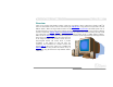
MK89-N / MK89-L / MK89-1394 Online Manual How Your Boot Screen Looks Like After you finish setting BIOS, these setting values will be displayed on the boot screen like the shown picture here. Every time you boot your system, both default and current settings will pop up on the screen. Your personal settings that had been adjusted earlier will be highlighted; thus, you can have clear idea how your system functions and monitor your system more easily.
MK89-N / MK89-L / MK89-1394 Online Manual D ri v e r a n d U t i l i t y There are motherboard drivers and utilities included in AOpen Bonus CD. You don’t need to install all of them in order to boot your system. But after you finish the hardware installation, you have to install your operation system first (such as Windows 2000/XP) before you can install any drivers or utilities. Please refer to your operation system’s installation guide.
MK89-N / MK89-L / MK89-1394 Online Manual NVIDIA NForce 3 Windows driver This Nvidia driver is an all in one package, which contains the below components: Audio driver, Audio utilities, GART driver, SMBus driver, Memory controller driver.
MK89-N / MK89-L / MK89-1394 Online Manual N V I DI A US B 2 . 0 d r i v e r NOTICE: If you have installed Windows XP Service Pack1, it is not necessary to install USB2.0 driver as USB2.0 driver is packed in Service Pack1 *********************************************** Installing Driver in Existing Windows XP System *********************************************** After enabling the USB 2.0, Windows XP setup will show a "Found New Hardware" dialog box.
MK89-N / MK89-L / MK89-1394 Online Manual For Windows98SE/ME, please install the driver from our bonus CD.
MK89-N / MK89-L / MK89-1394 Online Manual I n s t a l l i n g L A N dr i v e r ( f o r M K 8 9 - N a n d M K8 9 - 1 3 9 4 ) For Windows98SE/ME/2000/XP users, please install the LAN driver from our bonus CD.
MK89-N / MK89-L / MK89-1394 Online Manual For Windows95/NT4.0 users, please follow the procedures below to install the LAN driver. [Windows95] Installing driver procedure on Microsoft Windows 95 : ----------------------------------------------------1. Ask you to select which driver you want to install, select "Driver from disk provided by hardware manufacturer". 2.
MK89-N / MK89-L / MK89-1394 Online Manual 5. Enter drive and pathname [CD-ROM]:\Driver\LAN\RTL8100\Windows\NT (for NT 4.0) which is the path where the setup file OEMSETUP.INF is located, and then choose the OK button. 6. The screen will appear "Select Line Speed" dialog box which is provide by RTL8139.SYS driver. The default value is "auto" so that the RTL8139 PCI Fast Ethernet adapter and its driver RTL8139.SYS will auto-detect the line speed, 10Mb or 100Mb, while the RTL8139.SYS is loading.
MK89-N / MK89-L / MK89-1394 Online Manual I n s t a l l i n g L A N dr i v e r ( f o r M K 8 9 - L ) For Windows XP users, please follow the procedures below to install the LAN driver. 1. Open the Device Manager and check if there is "Ethernet Controller" in "Other devices". 2. Insert the supplied "Bonus CD". Right click "Ethernet Controller ", then select "Update Driver". 3. Select "Install from a list or specific location (Advanced)", and then click "Next".
MK89-N / MK89-L / MK89-1394 4. Online Manual Choose "Search for the best driver in these locations", and then select "Include this location in the search:" Type "G:\Driver\LAN\RTL8100S-32\WinXP" in the text box that appears. Press " Next ". 5.
MK89-N / MK89-L / MK89-1394 Online Manual For Windows 2000 users, please follow the procedures below to install the LAN driver. 1. Open the Device Manager and check if there is a "Ethernet Controller" in "Other devices" 2. Insert the supplied "Bonus CD". Right click "Ethernet Controller ", then select "Update Driver". 3. Click "Reinstall Driver" in the General Tab.
MK89-N / MK89-L / MK89-1394 4. Online Manual Select "Specify a location", and then click "Next". Type "G:\Driver\LAN\RTL8100S-32\Win2000" in the text box that appears. Press " OK".
MK89-N / MK89-L / MK89-1394 5.
MK89-N / MK89-L / MK89-1394 Online Manual For Windows ME users, please follow the procedures below to install the LAN driver. 1. Open the Device Manager and check if there is a "PCI Ethernet Controller" in "Other devices" 2. Insert the supplied "Bonus CD". Double click "PCI Ethernet Controller ", and click "Reinstall Driver" in the General Tab.” 3. Select "Specify the location of the driver (Advanced)".
MK89-N / MK89-L / MK89-1394 Online Manual 7. Driver installed. Restart computer.
MK89-N / MK89-L / MK89-1394 Online Manual For Windows 98 users, please follow the procedures below to install the LAN driver. 1. Open the Device Manager and check if there is a "PCI Ethernet Controller" in "Other devices" 2. Insert the supplied "Bonus CD". Double click "PCI Ethernet Controller ", and click "Reinstall Driver" in the General Tab.” 3. Select "Search for a better driver than the one your device is using now.
MK89-N / MK89-L / MK89-1394 Online Manual 4. Select "Specify a location", and type "G:\Driver\LAN\RTL8100S-32\Win98" in the text box that appears. Press " Next". System will ask you to provide the file path for loading driver. Please type "G:\Driver\LAN\RTL8100S-32\Win98" in the text box that appears and press " OK". System will ask you to insert "Windows 98 CD-ROM". 5. Driver installed. Restart computer.
MK89-N / MK89-L / MK89-1394 Online Manual For Windows NT users, please follow the procedures below to install the LAN driver. 1. In the Control Panel, double-click the Network icon. When the Network window opens, select the Adapters tab. 2. Click "Add" to install a new adapter. All previously installed drivers are listed under Network Adapters.
MK89-N / MK89-L / MK89-1394 Online Manual 3. When the Select Network Adapter window opens, click "Have Disk". When prompted, insert the BONUS CD. Type the path "G:\Driver\LAN\RTL8100S-32\Winnt4" to the driver, and click "OK". 4. With "Realtek RTL8169/8110 Family Gigabit Ethernet NIC" highlighted in the Select OEM Option window, click "OK".
MK89-N / MK89-L / MK89-1394 5.
MK89-N / MK89-L / MK89-1394 Online Manual G l os s a r y A C 9 7 C O DE C Basically, AC97 CODEC is the standard structure of PCI sound card. As we know, computer is digital-based, but music is based on analog-based. Therefore, there must be a process to turn digital into analog during the last stage processing of sound in computer. Hence, the component on sound card that play this important task is what we called CODEC.
MK89-N / MK89-L / MK89-1394 Online Manual A GP ( A c c e l e r a t ed Gr a p h i c P o r t ) The main function of AGP simply put is to tell monitor what screen information had to be shown, a visual transmission device actually. With the rapid developing of AGP card, we can see that it had been developed from single colorful AGP card to 2D and 3D graphic. AGP supports only memory read/write operation and single-master single-slave one-to-one only.
MK89-N / MK89-L / MK89-1394 Online Manual and integrated drive controller and the computer's motherboard. Two drives (master and slave) are supported. The ATA specification allows the drive to connect directly to the ISA bus on the computer. ATA transfer rate then had been developed to 133MHz/Sec and would come out with fastest rate later (please refer to Serial ATA). DMA, data transfer rate is 16.6MHz/s. Ultra DMA, data transfer rate is 16.6MHz x 2 = 33MB/s. ATA/66, data transfer rate is 16.
MK89-N / MK89-L / MK89-1394 Online Manual high transfer rate of 1MB/s, it also could be encrypted with pin code. With hopping rate of 1600 hops per second, it’s difficult to be intercepted and are less interrupted by electromagnetic wave.
MK89-N / MK89-L / MK89-1394 Online Manual E C C (E r r o r C h e c ki n g an d C o r r e c ti o n ) The ECC mode needs 8 ECC bits for 64-bit data. Each time memory is accessed; ECC bits are updated and checked by a special algorithm. The ECC algorithm has the ability to detect double-bit error and automatically correct single-bit error while parity mode can only detect single-bit error. E E P R O M (E l e c t r o n i c E r a s ab l e P r o g r am m a b l e RO M ) Also known as E 2PROM.
MK89-N / MK89-L / MK89-1394 Online Manual F C C D o C ( D e c l a r a ti o n o f C o n f o r m i t y ) The DoC is component certification standard of FCC EMI regulations. This standard allows DIY component (such as motherboard) to apply DoC label separately without a shielding of housing. F C -P GA (F l i p C h i p -P i n G r i d A r r a y ) FC means Flip Chip, FC-PGA is a package of Intel for Pentium III for 0.18µm process CPU, which can be plugged into SKT370 socket.
MK89-N / MK89-L / MK89-1394 Online Manual I E E E 1 3 94 IEEE 1394, which also called Firewire, is a serial data transfer protocol and interconnection system. The main feature of the Firewire that assures its adoption for the digital video and audio (A/V) consumer application is its low cost.
MK89-N / MK89-L / MK89-1394 Online Manual P C I ( P e r i p h e ra l C o m p o n en t I n t e r f a c e ) B u s Developed by Intel, Peripheral Component Interconnect (PCI) is a local bus standard. A bus is a channel used to transfer data to (input) and from (output) a computer and to or from a peripheral device. Most PCs have a PCI bus usually implemented at 32-bits providing a 33 MHz clock speed with a throughput rate of 133 MBps.
MK89-N / MK89-L / MK89-1394 Online Manual P S B (P r o c e s so r S y s t em B u s ) C l o c k PSB Clock means the external bus clock of CPU. CPU internal clock = CPU PSB Clock x CPU Clock Ratio R D R A M ( R am b u s D y n am i c R a n d o m A c c e ss M em o r y ) A DRAM technology developed by Rambus Corporation*, to achieve high speed of memory through the use of multiple channels in parallel by 16-bits. Basically, RDRAM uses new structure of Multibank, which is quite different from FPM, EDO, SDRAM.
MK89-N / MK89-L / MK89-1394 Online Manual SATA (S eri al ATA) The Serial ATA specification is designed to overcome speed limitations while enabling the storage interface to scale with the growing media rate demands of PC platforms. Serial ATA is to replace parallel ATA with the compatibility with existing operating systems and drivers, adding performance headroom for years to come. It is developed with data transfer rate of 150 Mbytes/second, and 300M/bs, 600M/bs to come.
MK89-N / MK89-L / MK89-1394 Online Manual system automatically recognize the change. USB 2.0, which supports data transfer rates of 480 Mbps, has been widely used in motherboard these days. VCM (Vi rtu al Ch ann el Mem o ry) NEC’s Virtual Channel Memory (VCM) is a new DRAM core architecture that dramatically improves the memory system’s ability to service multimedia requirements.
MK89-N / MK89-L / MK89-1394 Online Manual T r ou b l e s h o o t i n g If you encounter any trouble to boot you system, follow the procedures accordingly to resolve the problem. Start Turn off the power and unplug the AC power cable, then remove all of the add-on cards and cables, including VGA, IDE, FDD, COM1, COM2 and printer. Make sure if all jumper settings are correct.
MK89-N / MK89-L / MK89-1394 Online Manual Continue Install the VGA card. Then connect your monitor and keyboard. Turn on the power Yes and check if the power supply and CPU fan work properly. No The problem is probably caused by power supply or motherboard failure. Please contact your reseller or local distributor for repairing.
MK89-N / MK89-L / MK89-1394 Online Manual Continue No Check if there is display? Perhaps your VGA card or monitor is defective. Yes Press and key at the same time, hold them and then press to reboot the system. Check if the system reboots? Yes Next 100 No It is very possible that your keyboard is defective.
MK89-N / MK89-L / MK89-1394 Online Manual Continue During system rebooting, press to enter BIOS setup. Choose “Load Setup Default”. Turn off the system and re-connect IDE cable. Check if the system can No reboot successfully? Yes Re-install the operating system such as Windows 98. End 101 The problem should be caused by the IDE cable or HDD itself.
MK89-N / MK89-L / MK89-1394 Online Manual T e ch n ic a l Su p p o r t Dear Customer, Thanks for choosing AOpen products. To provide the best and fastest service to our customer is our first priority. However, we receive numerous emails and phone-calls worldwide everyday, it is very hard for us to serve everyone on time. We recommend you follow the procedures below and seek help before contact us. With your help, we can then continue to provide the best quality service to more customers.
MK89-N / MK89-L / MK89-1394 5 6 Online Manual eForum: We welcome you to join AOpen eForum to discuss our products with other users. Your problem probably had been discussed before or will be answered by other power users here. http://club.aopen.com.tw/forum/ Contact Distributors/Resellers: We sell our products through resellers and integrators. They should know your system configuration very well and should be able to solve your problem efficiently and provide important reference for you.
MK89-N / MK89-L / MK89-1394 Online Manual Mo d e l n a m e a n d B I O S v e r s i o n Model name and BIOS version can be found on upper left corner of first boot screen (POST screen). For example: MK89-N R1.02 Aug. 01.2003 AOpen Inc. Award Plug and Play BIOS Extension v1.0A Copyright © 2003, Award Software, Inc. MK89-N is model name of motherboard, R1.02 is BIOS version.
MK89-N / MK89-L / MK89-1394 Online Manual Produ c t R egis tration Thank you for choosing AOpen product. AOpen encourages you to spend few minutes in completing the following product registration. To register your product will ensure the high quality of services from AOpen. After the registration, you will: • Have opportunities to play online slot machine and win a prize from AOpen by accumulating your bonuses for later prize exchange. • Be upgraded to gold membership of Club AOpen program.
MK89-N / MK89-L / MK89-1394 Online Manual H o w t o C o n t ac t U s Please do not hesitate contact us if you have any problem about our products. Any opinion will be appreciated. America Pacific Rim Europe AOpen Inc. AOpen Computer b.v. AOpen America Inc. Tel: 886-2-3789-5888 Tel: 31-73-645-9516 Tel: 1-510-489-8928 Fax: 886-2-3789-5899 Email: Support@AOpen.NL Fax: 1-510-489-1998 China Germany Japan 艾爾鵬國際貿易(上海)有限公司 AOpen Computer GmbH. AOpen Japan Inc.