Table of Contents Table of Contents Table of Contents ................................................................................... 1 1.1 A Thank-you Note Before You Get Start..........................................................3 1.2 Features of This Manual ...............................................................................4 1.3 Safety Information ......................................................................................4 Chapter 2 Introduction to This Motherboard .....
Connecting S/PDIF (Sony/Philips Digital Interface) ........................................24 Colored Coded Back Panel ..........................................................................25 LED Indication ..........................................................................................26 3.4 Jumper Settings ........................................................................................ 27 Chapter 4 Special Features and Utilities...................................................
1.1 A Thank-you Note Before You Get Start First of all, we would like to express our gratitude for purchasing AOpen products. Once again, this motherboard is designed uniquely to meet all your personal needs with our great industry-designing ability and our everlasting perseverance to the quality of all our products. This manual will introduce you how this motherboard is installed. Please keep it well for your future reference. If you lost your printed manual, you may also go to our website at http://www.
1.2 Features of This Manual To help you grab the useful information of this motherboard and aware of certain conditions that you might need to know, you will see the icons below frequently: Note This contains knowledge you should know in process of assembling, or some helpful tips. Warning / Caution Warning Please be careful when you see this mark. highlights mistakes that occur often It during assembling, or something you need to pay attention to.
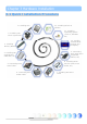
Chapter 2 Introduction to This Motherboard Chapter 2 Introduction to This Motherboard 2.1 How does your motherboard look like? 13 15 17 19 21 14 16 1 2 18 5 20 6 22 23 25 27 3 4 8 24 9 10 26 11 12 28 1. SYSFAN1 Connector 7 15. Front Audio Connector 2. Resetable Fuse 16. Onboard AC’97 CODEC 3. COM2 Connector 17. CD_IN Connector 4. 4-pin 12V ATX Power Connector 18. SIS 10/100Mbps LAN Chip 5. AGP 4X Expansion Slot 6. 478-pin CPU socket supporting Intel P4 CPU 7.
2.2 Specification Here is the main function of your motherboard. Models CPU Chipset Main Memory Graphics IDE LAN Sound USB Slots Back Panel I/O On Board Connector BIOS Board Size s651m Intel Pentium 4 CPU Socket 478 400/533MHz Intel 651/962L Dual Channel Mode DDR 266/333MHz DDR DIMM x 2 DIMM Type : 64/128/256/512MB & 1GB Max Memory : 2GB Integrated VGA Engine in chipset 4X AGP slot Integrated ATA133 Controller Max Disk: 144,000,000GB [by 48 bits LBA Spec.
2.
Chapter 3 Hardware Installation Chapter 3 Hardware Installation 3.1 Quick Installation Procedure 12. Installing Drivers & Utilities 1. Installing CPU 11. Installing Operating System (such as, Windows XP) 2. Installing CPU Fan & System Fan 3. Installing Memory Module 10. Loading Default BIOS, Setting CPU Frequency 4. Installing HD, CD-ROM and SATA Disk, etc 9. Connecting Back Panel Ports (Keyboard, Mouse, etc) 8. Installing Other Devices (USB, Front Audio, etc) 5. Connecting Front Panel Cable 7.
3.2 Installation You Have to Know Installing CPU This socket supports FC-PGA2 package CPU, which is the latest CPU package developed by Intel. Other forms of CPU package are impossible to be fitted in. 1. Pull up the CPU socket lever and up to 90-degree angle. 2. Locate Pin 1 in the socket and look for a golden arrow on the CPU upper interface. Match Pin 1 and golden arrow. Then insert the CPU into the socket. 3. Press down the CPU socket lever to finish CPU installation.
Installing CPU and System Fans Plug the CPU fan cable to the 3-pin CPUFAN connector. If you have chassis fan, you can also plug it in SYSFAN1 or SYSFAN2 connector. GND +12V SENSOR SYSFAN1 Connector GND +12V SENSOR GND CPUFAN Connector +12V SENSOR SYSFAN2 Connector Note: Some CPU fans do not have sensor pin so that they cannot support fan monitoring.
Installing Memory Modules DIMM slots are designed in black which are very easy to recognize. Insert the module straight down to the DIMM slot with both hands and press down firmly until the DIMM module is securely in place. Tab Pin 1 Key Note: The tabs of the DIMM slot will clip to hold the DIMM in place when the DIMM touches the slot’s bottom.
Connecting IDE and Floppy Cables Connect the 34-pin floppy cable and 40-pin, 80-wire IDE cable to floppy connector and IDE connector. Be careful of the pin1 orientation. Wrong orientation may cause system damage.
Connecting Front Panel Cable Attach the power LED, speaker and reset switch connectors to the corresponding pins. If you enable “Suspend Mode” item in BIOS Setup, the ACPI & Power LED will keep flashing while the system is in suspend mode. Locate the power switch cable from your ATX housing, which is a 2-pin female connector from the housing front panel. Plug this connector to the soft-power switch connector marked SPWR.
Connecting ATX Power Cables This motherboard comes with a 20-pin and 4-pin ATX power connector as shown below. Make sure you plug them in the right direction. We strongly recommend you to insert the 4-pin connector before connecting the 20-pin connector.
3.3 Other Installation for Your Reference Setting CPU Voltage and Frequency Setting CPU Core Voltage This motherboard supports Voltage ID (VID) function to detect CPU voltage automatically during power-on. Setting CPU Frequency This motherboard is of CPU jumper-less design; you can set CPU frequency by 1MHz stepping CPU Overclocking in the BIOS. CPU Core Frequency = CPU FSB clock x CPU Ratio. However, all CPU now sold in market belong to "Fixed Multiplier".
Connecting AGP 4X Expansion Slot s651m provide an AGP 4X slot. The AGP 4X is a bus interface targeted for high-performance 3D graphic, and the data transfer rate could achieve 66MHz x 4bytes x 4 = 1056MB/s.
Connecting CNR (Communication and Network Riser) Expansion Slot CNR is a riser card specification to replace the AMR (Audio/Modem Riser) that supports V.90 analog modem, multi-channel audio, and phone-line based networking. Owing to CPU computing power getting stronger, the digital processing job can be implemented in main chipset and share CPU power. The analogy conversion (CODEC) circuit requires a different and separate circuit design, which is put on CNR card.
Connecting IrDA The IrDA connector can be configured to support wireless infrared module, with this module and application software such as Laplink or Windows Direct Cable Connection, user can transfer files to or from laptops, notebooks, PDA devices and printers. This connector supports both HPSIR (115.2Kbps, 2 meters) and ASK-IR (56Kbps). Install an infrared module onto the IrDA connector and enable the infrared function from BIOS Setup, UART Mode, you can use this function.
10/100Mbps LAN Supported On the strength of 10/100Mbps LAN controller on board, this motherboard provides 10/100Mbps Ethernet for office and home use. The Ethernet RJ45 connector is located on the top of USB connectors. The right hand side LED indicates link mode; it lights in yellow when linking to network. The left hand side LED indicates the transfer mode and will light in green when data is transferring at 100Mbps (never lights while at 10Mbps).
Connecting COM2 This motherboard provides two serial ports. One of them is on back panel connector, and the other is on the upper left of board between PCI slots. With proper cable, you can connect it to the back panel of chassis.
Connecting USB2.0 This motherboard provides six USB 2.0 ports to connect USB devices such as mouse, keyboard, modem, printer, etc. There are four ports on the back panel. You can use proper cables to connect Front USB connector to USB modules or chassis front panel.
Connecting Front Audio If the housing is designed with an audio port on the front panel, you’ll be able to connect onboard audio to front panel through this connector. By the way, please remove the jumper cap from the Front Audio Connector before you connect the cable. Do not remove this yellow jumper cap if your housing doesn’t have an audio port on the front panel.
Connecting CD_IN This connector is designed to connect CD Audio cable from CDROM or DVD drive to onboard sound.
Connecting S/PDIF (Sony/Philips Digital Interface) S/PDIF (Sony/Philips Digital Interface) is a newest audio transfer file format, which provides impressive audio quality through optical fiber and allows you to enjoy digital audio instead of analog audio. Through a specific audio cable, you can connect the S/PDIF connector to other end of the S/PDIF audio module, which bears S/PDIF digital output.
Colored Coded Back Panel The onboard I/O devices have PS/2 Keyboard, PS/2 Mouse, RJ-45 LAN Connector, COM1, VGA port, Printer, USB, AC’97 sound and game ports. The view angle of drawing shown here is from the back panel of the housing. PS/2 Mouse Connector USB 2.
LED Indication LED indication are AOpen’s considerate designs that aim at providing you friendly system information. STBY LED will light up when power is provided to the motherboard, giving you a convenient indication check the system power status in circumstances such as power on/off, stand-by mode and RAM power status during Suspend to RAM mode. AGP LED aims to protect your motherboard from being damaged by over voltage of AGP card.
3.4 Jumper Settings This motherboard provides PS2 keyboard / mouse wake-up function. JP28 Keyboard / Mouse Wakeup Jumper JP28 PS2 KB/Mouse Wakeup Jumper 1 Disable (Default) 1 1 Enable 1 JP14 Clear CMOS Jumper Normal Clear CMOS (default) You can clear CMOS to restore system default setting. To clear the CMOS, follow the procedure below. JP14 Clear CMOS Data 1. Turn off the system and unplug the AC power. 2. Remove ATX power cable from connector PWR2. 3.
Chapter 4 Special Features and Utilities Chapter 4 Special Features and Utilities Other Useful Features With excellent design ability of R&D team, AOpen boasts for its various powerful and handy features that come with our product like follows. You are welcomed to visit our technical website to learn more about those features. http://english.aopen.com.
Chapter 5 Setting BIOS Chapter 5 Setting BIOS Introduction System parameters can be modified by going into BIOS Setup menu; this menu allows you to configure the system parameters and save the configuration into the 128 bytes CMOS area (normally in the RTC chip or in the main chipset). The Phoenix-Award BIOS™ that installed in the Flash ROM of the motherboard is a custom version of an industry standard BIOS.
How To Use Phoenix-Award™ BIOS Setup Program Generally, you can use arrow keys to highlight items that you want to choose, press key to select, and use and keys to change setting values. You can press key to quit Phoenix-Award™ BIOS setup program. The following table provides details about how to use keyboard in the Phoenix-Award BIOS setup program.
BIOS Upgrade under Windows environment With outstanding R&D ability of AOpen, we now bring you a whole new BIOS Flash wizard ---- EzWinFlash. With an eye to convenience for users, EzWinFlash combines the BIOS binary code and flash module together, so the only thing you have to do is just clicking on the utility you downloaded from web and let it help you complete the flash process automatically.
You may accomplish BIOS upgrade procedure with EzWinFlash according to following steps, and it’s STRONGLY RECOMMENDED to close all applications before you start the upgrades. Download the latest version of BIOS package zip file from AOpen official web site. (Ex: http://english.aopen.com.tw/) Unzip the downloaded BIOS package (ex: WS651M102.ZIP) with WinZip (http://www.winzip.com) in Windows environment. Save the unzipped files into a folder, for example, WS651M102.EXE & WS651M102.BIN.
Vivid BIOS technology Have you been fed up with the conservative and immutable POST screen? Let’s rule out the tradition idea that POST screen are stiff and frigid, and let AOpen show you the newly developed VividBIOS to experience the lively vivid colorful POST screen! Unlike earlier graphic POST screen which could occupy the whole screen and mask text information during POST, AOpen VividBIOS deals with graphics and texts separately, and makes them running simultaneously during POST.
Chapter 6 Installing Drivers Chapter 6 Installing Drivers You may think that installing drivers and utilities would be a repeated task of going through those installation wizards and steps-by-steps. Now, you will be surprised with how “Ez” EzInstall could do. Without wizards or steps, all you have to do is to do one click and then it’s done. Click and done. Yes.
6.1 Installing Drivers As you may see from the Installing driver page, EzInstall had picked up necessary for your motherboard. All you have to do is just click on the “GO”, and no more steps afterward, of all listed drivers, grey checks indicate necessary drivers; you cannot click them off. Red checks can be disabled if you don’t want to install them now. Press the icon will prompt the “Install Driver” page. You may also press “Back” to return to the Main page.
6.2 Installing Utilities Installing Utilities is virtually the same as installing drivers. AOpen provides you many friendly and powerful utilities to manage your system. You may find lots of fabulous utilities listed there, and all you have to do is to click on the “GO”, then it will install the utilities to your system right away without complicated steps. Press prompt the the icon will “Install Utilities” page for your selection. You may also press “Back” to get back to the Main page.
Chapter 7 Troubleshooting Chapter 7 Troubleshooting 37
Chapter 8 Technical Support Chapter 8 Technical Support Dear Customer, Thanks for choosing AOpen products. We invite you to register at http://www.aopen.com to become a Gold Member of Club AOpen so as to ensure quality service in the future. In order to maintain the best service to every customer of us, we recommend you to follow the procedures below and seek help from our branches according to the region you buy the product.
Model Name and BIOS Version Model name and BIOS version can be found on upper left corner of first boot screen (POST screen). For example: Phoenix AwardBIOS v6.00PG, An Energy Star Ally Copyright (C) 2003, Phoenix Technologies, LTD. s651m R1.02 Mar. 01. 2003 AOpen Inc. s651m is model name of motherboard; R1.02 is BIOS version Register Your Motherboard Thanks for choosing AOpen product, please register this motherboard at http://club.aopen.com.
Technical Support 40