
User Guide


Hardware Installation
2-13
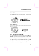
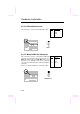
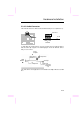
2.3.10 Panel Connector
The Panel (multifunction) connector is
a 20-pin connector marked as PANEL
on the board. Attach the power LED,
keylock, speaker, SPWR, IDE LED
and reset switch to the corresponding
pins as shown in the figure.
If your ATX housing supports ACPI
specification, the ACPI & Power LED
will keep flashing if you have enabled
“suspend mode” item in the BIOS
Setup.
1
SPWR
GND
ACPI & POWER LED
GND
+5V
NC
NC
GND
RESET
GND
11
10 20
GND
KEYLOCK
+5V
IDE LED
IDE LED
+5V
+5V
GND
NC
SPEAKER
PANEL
1
Speaker
IDE LED
Keylock
Reset
11
10
20
+
+
+
+
SPWR
+
+
ACPI &
Power LED
PANEL