C h apt er 2 Hardware Installation Electrostatic discharge (ESD) can damage your processor, disk drives, expansion boards, and other components. Always observe the following precautions before you install a system component. 1. Do not remove a component from its protective packaging until you are ready to install it. 2.
! " ! " $ '( ) *+, ! # ! !,( # % & # '- '- # !(,. !(,- + / " 0 1.
6 7 8 # 9 7 ( 9 # .
! " %) & 9 + ! "9 : ; )
()* ! "" ' ! " # 5 ! " 9 ! " !" # $$ ! ! # $$ !
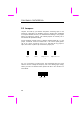
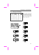
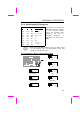
Normally, for single voltage CPU, Vcpuio (CPU I/O Voltage) is equal to Vcore, but for CPU that needs dual voltage such as PP/MT (P55C) or Cyrix 6x86L, Vcpuio is different from Vcore and must be set to Vio (PBSRAM and Chipset Voltage). The single or dual voltage CPU is automatically detected by hardware circuit. For supporting more different CPUs in future, this motherboard uses five switches to specify Vcore. There are 32 settings totally, and the range is from 1.3V to 3.5V.
! " .
$ & $ , & $ + & ( ) (* ( ) (* 9 ! $ >$;> +, ?='?> ! " %! & 1$ %0 & 8 ! '0 8
! " ! " $% &' $% ( $% ) ) ) ) #-. #-. #-. #-. #-. #-. + #-. + #-. #-. #-. #-. #-. #-. #-. #-. ""#-. #-. #-. #-. + #-. +#-. #-. # . #-.
) #-. #-. #-. ""#-. #-.
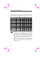
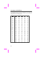
The following table are possible settings of current CPU available on the market. The correct setting may vary because of new CPU product, refer to your CPU specification for more details.
"$$ "$$ +, - " ( +, "! . "! . "! . "! " " +, - ( +, "! . "! . "! . "! " " ( +, "! . "! . "! . "! $$ $$ +, - ( +, "! . "! . "! . "! " ( +, "! . "! . "! .
1! 2 $$ +,- +,- ( ( 0 +, +, "! . ! . "! . "! "! . "! . "! . "! + & !" $ " $ +, - ( 0 +, "! . ! . "! . "! ! $$ $$ +, - ( +, "! . "! . "! . "! , ' + -% 2"$$ "$$ +, - " ( +, "! . "! . "! .
! $ $ +, ( % +, ! . "! . ! . ! ! $$ $$ +, ( "$$ +, "! . "! . ! . ! ! $ $ +, ( "$$ +, "! . "! . ! . ! ! $$ $$ +, ( "$$ +, "! . "! . ! . ! ! $ $ +, "$$ +, "! . "! . ! .
12 0 ) , +- 3 4 $' 5 3 & A !,( !,( 9 3 # ) ) 3 4 $' 5 3 & 3 # ! " #$!%& ! '# $(!) .
! "# ) (.- , / 0 *+, %) & ! "9 6 .
$ % + / -C , # Make sure that the power supply is off before connecting or disconnecting the power cable.
# 9 A ! " - ! " +5.
! + % , '- # > , # # - . * / # 0 D # .
1 -= # # 2 3 . A " 0 " 0 " 0 9 # * 4 55 .
* 6 8 , * , " 7 :C 1 # * 1.
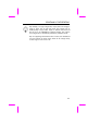
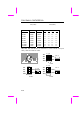
: The specification of IDE cable is maximum 46cm (18 inches), make sure your cable does not excess this length. For better signal quality, it is recommended to set far end side device to master mode and follow the suggested sequence to install your new device. Please refer to following figure.
6 6 6 6 4 6 6 4 % & -C # + 31 9 # #9 # 9 # # 31 31 # # 9 #
( .
: ) 5 , * ( 9 , ! %+( , =>& $ $ , , 9 , +( , =>9 : , , => " + .
$&170%
B- ,, # % , , & .>; ,, # % , , & $ .@0 ,, : # * -.! 9 .,$<- %:,0&9 :,$<- %.>,0&9 .>,$<- %>:,0&9 9 .,$<-$- %;,0&9 :,$<-$- %<-,0&9 .>,$<-$- %.
* "!!% # .-9 # .- $ # *+, ;<,27 *+, # >B9 $ # >B 7 Some SDRAMs marked as -10 may work fine with 100 MHz CPU clock, but not all this kind of modules can work properly under 100MHz external clock.
To identify 2-clock and 4-clock SDRAM, you may check if there are traces connected to golden finger pin 79 and pin 163 of the SDRAM. If there are traces, the SDRAM is probably 4clock; Otherwise, it is 2-clock. 0* ) -'/ >: % & *+, 8 7 0 ( #')( !7# / -.! 8 -.! #1 9 -.! #1 9 -.
kind of SDRAM. The DIMM chip count can be calculated by following example: 1. For 32 bit non-parity SIMM using 1M by 4 bit DRAM chip, 32/4=8 chips. 2. For 36 bit parity SIMM using 1M by 4 bit DRAM chip, 36/4=9 chips. 3. For 36 bit parity SIMM using 1M by 4 bit and 1M by 1 bit DRAM, the chip count will be 8 data chips (8= 32/4) plus 4 parity chips(4=4/1), total is 12 chips. 4. For 64 bit DIMM using 1M by 16 bit SDRAM, the chip count is 64/16=4 chips.
,, *+, ,, ' ' + 0 . ' ' 0 . 1 . 2 3 4 + 5 2 0 .
5& ( + ' ' + 0 . ( " 4 6 7 1 . 2 3 4 + 5 2 0 .
5& ( " 5& " ( ( 4 (" " " 4 .CC,27 $ #9 ! .CC *+, ! .