® AR-STV WIRELESS CAMERA DETECTOR Operating manual AOR, LTD.
TABLE OF CONTENTS 1 Introduction -------------------------------------------------------------------------------------1-1 Maintaining the unit --------------------------------------------------------------------------1-2 Power requirements -------------------------------------------------------------------------1-3 Supplied accessories -----------------------------------------------------------------------1-4 Features -----------------------------------------------------------------------------------------
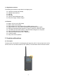
1 Introduction Thank you for purchasing the AR-STV Wireless Camera Detector. The AR-STV is a wireless camera receiver with a 2.5 inch color LCD display, still picture recorder and sensor that captures analog video signals in real-time. It is mainly designed for use in surveillance applications. Its built-in clock allows images to be time-stamped and a (non-supplied) SD memory card can be used to store images. © This manual is protected by copyright AOR, LTD. 2013.
1-3 Supplied accessories The following accessories are provided in the shipping box. Instruction manual (this booklet) Flexible rubber antenna Belt clip Soft case Four AA size Ni-MH battery cells DC power supply / battery charger 1-4 Features Built-in 2.
Left View Right View Right Side of the AR-STV 1 Power ON/OFF switch Slide the power switch upward to switch on the AR-STV. To switch off the AR-STV, slide the switch downward. 2 CONT (USB connector) Using a USB A ←→ USB Mini (B) cable (not supplied), connect between the CONT (Control) connector and a PC to download images which have been previously 3 VIDEO (Video Output connector) This 3.5 mm mono connector provides the composite video output. An external video monitor may be connected.
4 DC 6V (External power input connector) To charge the internal Ni-MH cells, connect the supplied DC power supply into this connector. Note that the center pin of the jack is positive. 5 SD (SD, SDHC memory card slot) Insert a (non-supplied) SD memory card (up to 32 GB) into this slot to save images. Approx. 20,000 images may be saved on a 1GB SD card. 6 ALM OUT (Alarm output connector) Connect an external alarm device into this connector. (Format: 3.
Left Side of the AR-STV 7 MODE (Mode selector) switch Press this switch to select the operation mode. 8 REC (Record) switch Press this switch to store image onto memory. 9 FREQ UP DOWN (Frequency selector switch) Press this switch upward/downward to change the receive frequency or change search direction. 2-2 Rear panel Battery compartment With the supplied belt clip attached.
3 Connections Connect the supplied flexible rubber antenna to the SMA antenna connector on the top of the ARSTV. If required, an external antenna may be connected with a SMA connector for the coaxial cable. Insert the supplied 4 AA size Ni-MH cells into the battery compartment in the AR-STV. If the batteries are not yet charged, connect the DC power supply into the power input connector on the right side. 4 Power switch To switch on the AR-STV, slide the power switch on the right side of the AR-STV upward.
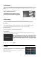
(1) 1G 2G 3G (Hz) The horizontal axis displays the receive frequency. The AR-STV can receive between 900 MHz and 2800 MHz. (1G indicates 1 GHz in frequency, 2 G for 2 GHz, and 3 G for 3 GHz accordingly.) (2) V (Video level) N (Noise level) Video Level The V (Video) line on the vertical axis displays the video quality threshold level. Note that video level is NOT related to the signal strength. Setting the video threshold level higher will display the video signal only with the better quality.
Icon legend: Signal level Battery level Search bank Receive freq. SD card inside Search mode 5-2-1-1 Frequency adjustment To change the receive frequency, press the FREQ. switch upward or downward. 5-2-1-2 Recording image To record the received image, press and hold the REC switch for 3 seconds. (Note: To record an image, a non-supplied SD memory card must be installed in the AR-STV. Otherwise, a beep will sound, and the SD Error message will appear on the LCD screen.
1. On the Search Mode screen, press and hold the MODE switch for 3 seconds 2. The following search bank setting screen will appear. Search: Search bank number 0 ~ 9. To change the search bank, press the MODE key. Start: Select the start frequency. (Frequency range: 900 ~ 2800MHz). On above example, 09 is highlighted in reverse color and 900 MHz has been set as the start frequency. To change the first 2 digits, press the FREQ. Switch inward.
Step: Select the search frequency step. (Entry range: 2 ~ 10 MHz) To change the parameter, perform the same procedures as the start frequency entry. Noise Level: Select the noise threshold level. (Entry range: -30 ~ -80 db min 5 dB increments) Suggested level: 75 (for normal search) 0 (for weak signal) Run: Select the search bank enable or disable. To change the parameter, perform the same procedures as the start frequency entry Video Level: Select the video threshold level.
Icon legend: Signal level Battery level Search bank Receive freq. SD card inside Search mode 5-2-2-1 Scroll memory channel To scroll the memory channel, press the FREQ. switch upward or downward. 5-2-2-2 Slide show To start a slide show of the recorded frequencies, press and hold the FREQ. switch for 3 seconds. 5-2-2-3 Change memory contents To change the recorded frequency of the memory channel, perform the following steps: 1. Press and hold the MODE switch for 3 seconds. 2.
To return to the search mode, press the MODE switch and REC switch simultaneously three times. (The operation mode will toggle between the Search mode, Memory mode, SD card mode, and setting mode.) 5-2-3 Setting mode There are two (2) setting pages: Setting 1 and Setting 2. 5-2-3-1 Setting 1 screen Press the MODE switch and REC switch simultaneously several times (depending on the current operation mode). (Press the blue button to proceed directly to the settings 2 screen if needed.
5-2-3-2 Setting 2 screen Press the MODE switch and REC switch simultaneously several times (depending on the current operation mode) until the SETTINGS 1 screen appears, then press the blue button to get to the SETTINGS 2 screen LCD/AVOUT: Video signal output selection. (Parameter LCD/ AV OUT) LCD: Displays on the LCD AV OUT: Output from the VIDEO jack. (Note: AV output is available only in the Search mode and Memory mode, and when the power is ON.) Alarm output: Alarm signal output selection.
OFF: Detected image will NOT be saved on the SD memory card automatically. NTSC/PAL: Video detector mode (Parameter: NTSC/ PAL) Select the video receive mode. Power Save: Battery power save function (Parameter: ON/ OFF) ON: To save battery consumption during search, the power to the LCD will be turned off. If there is no activity for more than 30 seconds, the power to the LCD will also be turned off. OFF: This function will be disabled. Relay: Activate / deactivate an alarm relay.
6 Specifications Frequency Coverage: Receive Mode: Receiving system: IF (Intermediate frequency): Memory channels: Search banks: Search speed: Frequency step: Sensitivity: Antenna impedance: Antenna connector: Antenna: Power requirements: External input voltage: Current drain: Operating environment: Relay output for alarm: Relay specs: Recording media: Picture size: Memory contents: Video output: Dimensions: Weight: 900 ~ 2,800 MHz continuous FM Video Single conversion super heterodyne 479.
7 LIMITED WARRANTY (for U.S.A only) AOR USA, Inc. (AOR) warrants its products as described below. AOR will repair or exchange equipment as a result of defects in parts or workmanship for a period of one year from the date of original retail purchase from an authorized AOR dealer. Exclusions: The following items are not covered by the AOR limited warranty: 1. Products that are damaged through accident, abuse, misuse, neglect, or user modifications. 2.
Manufacturer: AOR, LTD. 2-6-4, Misuji, Taito-Ku, Tokyo, 111-0055, Japan URL: www.aorja.com US distributor: AOR USA, INC. 20655 S. Western Ave. Suite 112 Torrance, CA 90501 Phone: 310-787-8615 Fax: 310-787-8619 URL: www.aorusa.com e-mail: info@aorusa.