
Specifications

111
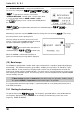
The centre frequency is displayed in the top left of the LCD, one pixel will be missing from the centre of
the graphical base line indicating centre frequency position.
A progress cursor which comprises of a single pixel on the graphical base line travels from left to right
updating the band scope display… this confirms that the band scope is IN OPERATION (especially
useful when a trace is simply being updated or no signals have been located).
The frequency span width is displayed in the upper right corner of the LCD, at default this is 10 MHz.
The frequency marker legend “MKR” is displayed on the second line of the LCD, the marker is also
represented graphically by an upturned triangle (initially placed above-centre of the graphical trace).
When first activated, the centre and marker frequencies are the same (but may be altered).
The graphical trace is built-up from left to right. If no transmissions are encountered the display will
simply form a horizontal line around two pixels in height. When activity is located, vertical lines are
produced on the LCD, the stronger the signal the higher the line.
Important: To monitor the transmission of the marker frequency and hold the
key. The progress of the scope is halted when the key is held. Squelch
setting has no effect on the band scope trace.
15-2 Exit from band scope
To exit the band scope or or .
15-3 Setting frequency span width (waveform enlargement)
The frequency span width may be adjusted between the limits of 10 MHz (default) to 100 kHz using
the keys. The span widths available are:
10 MHz 35s for full trace approx.
5 MHz 20s for full trace approx.
2 MHz 10s for full trace approx.
1 MHz 6s for full trace approx.
500 kHz 3s for full trace approx.
200 kHz 6s for full trace approx.
100 kHz. 3s for full trace approx.
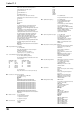
Section 15-1, 15-2, 15-3
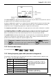
Resolution is 10 kHz with a 12 kHz IF
filter selected (NFM or AM) so that one
pixel represents 140 kHz at maximum
signal strength
Resolution is 2 kHz with a
3 kHz filter (USB, LSB, CW)