MAGNETIC LOOP ANTENNA LA400 Instruction manual AOR Ltd.
Table of contents 1. Introduction ......................................... 4 2. Included in this package . . . . . . . . . . . . . . . . . . . . . . . . . . . . . . . . . 5 3. Hardware setup . . . . . . . . . . . . . . . . . . . . . . . . . . . . . . . . . . . . . . 6 4. Operating instructions . . . . . . . . . . . . . . . . . . . . . . . . . . . . . . . . . . 7 5. Remote tuning system . . . . . . . . . . . . . . . . . . . . . . . . . . . . . . . . . 9 6. Directivity of a loop antenna . . . . . .
1. Introduction Thank you for purchasing the LA400 Magnetic loop antenna. To get the best possible results from your LA400, we recommend that you read this manual and familiarize yourself with the antenna. Since the invention of this revolutionary concept by KOLSTER in 1915, loop antennas, especially of the active type, have also been widely used by the military in the 70’s, before becoming very popular among hobby listeners.
2. Included in this package No.
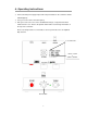
3. Hardware setup Caution! LA400 is a RECEIVE ONLY antenna. Do not transmit with it or its circuitry will be severely damaged, maybe even beyond repair. As explained on the diagram below, attach the loop element to the control box, then connect the coaxial and control cables. Finally, connect the AC power supply. To connect LA400 to an antique receiver with 600Ω antenna terminal, use the optional MC-600 Impedance Matching Transformer.
4. Operating instructions ◎ Connect the AC power supply and push the red power button on the control box. A blue LED will light up. ◎ Tune your receiver to the desired frequency. ◎ Now you need to select one of the 5 available band ranges, using the band switch numbered from 1 to 5. Refer to the printed switch number / band range information on the top of the control box. Please note that position 5 is non-tunable, as the loop is wired to act as an amplified whip antenna.
◎ Peak the received signal by turning the TUNING knob slowly to either the left or the right. The white dot on the tuning know helps you to see the approximate location of the tuning. For your reference, when the dot is on top as on the above illustration, the tuning PEAK is approximately in the middle of the selected band. For example for band switch position 3 (3MHz to 10MHz), it would be roughly peaked on 6.5MHz. Tuning is most critical above 3MHz.
5.Remote tuning system With its unique REMOTE TUNING SYSTEM, the band switching and fine tuning controls are not tied anymore to the loop element. With these controls now on the control box and by using the optional LA400-RCK extension cables, it is now possible to tune the antenna while the loop element is setup at the most reception friendly location possible (window, covered balcony, etc...). You can of course use generic straight LAN and RG-58U 50Ω coaxial cables. Maximum length: 20m each.
6. Directivity of a loop antenna A significant advantage of a loop antenna is its directional pattern, a “figure 8” shape with two null points separated by 180 degrees. The null in reception that is located at right angles to the plane of the loop can be used for interference reduction. On the other hand, received signal strength is greatest in the directions indicated by the arrows.
7. Characteristics of a “shielded” loop antenna A shielded loop antenna is less susceptible to nearby electrical interference sources, thanks to the electrostatic shielding of the loop afforded by the grounded metallic conduit enclosing the wire coils. By these principles, LA400 responds to the magnetic field rather than the electric field, thus efficiently isolating the low frequency electrostatic noise from the distant signal to be received.
8. Options LA400-RCK Extension cables (10m each) This set of cables allows you to separate the control (tuning) box from the loop element, by up to 10m. Conveniently place the loop element as closely as possible to an open space, such as window, covered balcony, etc...away from local electrical noise, for a quieter reception experience.
9. Specifications LA400 Magnetic loop antenna Frequency range 10kHz 〜 500MHz Aligned range 150kHz 〜 30MHz Unaligned range 10kHz 〜 150kHz, 30MHz 〜 500MHz Gain 20dB min. Operating temp. -10℃ 〜 +60℃ Power req. 9〜15V DC, 80mA @ 12VDC Impedance 50Ω 4 band selectable Loop 305mm diameter Sizes (mm) Loop element 305(W)x367(H)x38(D) projections incl.
® AOR Ltd. 2-6-4 Misuji, Taito-ku, 111-0055 Tokyo, Japan www.aorja.