AOYUE ® INT 968A+ Deluxe Repairing System INSTRUCTION MANUAL Thank you for purchasing Aoyue INT 968A+ Repairing System. It is important to read the manual before using the equipment. Please keep manual in accessible place for future reference. Manufacturer: AOYUE INTERNATIONAL LIMITED Jishui Industrial Zone, Nantou, Zhongshan City, Guangdong Province, P.R.China http://www.aoyue.
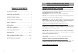
BASIC TROUBLESHOOTING GUIDE PROBLEM 5: AIR PRESSURE LEVEL IS SIGNIFICANTLY LOW NO MATTER HOW HIGH THE AIRFLOW LEVEL IS CALIBRATED TABLE OF CONTENTS PACKAGE INCLUSION ………………..………….. Case 1: Check the mains voltage (AC power source). If the voltage level 3 FUNCTIONS AND FEATURES ……………….......... 4 PRODUCT SPECIFICATIONS …….………...……… 5 CARE AND SAFETY PRECAUTIONS ………..………. 6 PANEL CONTROLS ………………………...…........ 7 PREPARATION ……………………………………… 8 OPERATING GUIDELINES ...…………………..
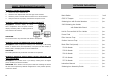
PACCKAGE INCLUSIONS BASIC TROUBLESHOOTING GUIDE PROBLEM 1: THE UNIT HAS NO POWER 1. Check if the unit is switched ON. 2. Check the fuse. Replace with the same type if fuse is blown. 3. Check the power cord and make sure there are no disconnections. 4. Verify that the unit is properly connected to the power source. Main Station ……………………………… 1 unit G001 IC Popper ……………………………… 1pc. PROBLEM 2: TEMPERATURE DISPLAY IS ALWAYS ABOVE 500oC Soldering Iron with Smoke Absorber …………… 1pc.
FUNCTION and FEATURES ● Micro-processor-controlled electro-static discharge (ESD) safe unit. ● Easy-to-use touch type panel controls with digital display for Hot Air Gun function. ● Environment-friendly repairing system that integrates Hot Air Gun, Soldering Iron, and Smoke Absorber in one package.
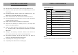
CARE and MAINTENANCE IMPORTANT: Unless otherwise directed, carry out these procedures with the power switched OFF and the power cord UNPLUGGED. SPECIFICATION Power Input : available in 110V & 220V Main Station Dimensions: CARBON FILTER 188(w) x 126(h) x 250(d) mm Weight: K1 — filter drawer K2 — active carbon filter pads (30181X) K3 — smoke absorption nozzle ● A filter device is installed at the vacuum outlet (see D2 of panel controls reference page) .
CARE and MAINTENANCE SAFETY PRECAUTIONS 1. Tip Temperature — High temperature shortens tip life and may cause CAUTION: Misuse can cause injury and other physical damage. thermal shock to other components. Always use the most appropriate For your own safety, be sure to observe the following precautions. temperature when soldering. Temperature may reach as high as 480°C when unit is turned ON. ● - Do not use near paper, plastic, and flammable gases and materials. sponges.
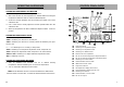
OPERATING GUIDELINES CONTROL PANEL GUIDE SOLDERING IRON MANUAL CALIBRATION C2 C3 1. Set Soldering Iron to desired working temperature. C1 2. Wait a few minutes for the temperature to stabilize before checking the temperature difference with an external calibrated probe. 3. Access the manual calibration hole by removing the rubber cover of the calibration hole. 4. Use a small screw to slowly adjust the trimmer potentiometer thru the calibration hole. 5. When tip temperature has been recalibrated.
ASSEMBLY and PREPARATIONS OPERATING GUIDELINES A. Main Power 1. ● indicating it is now on digital calibration mode. Plug power cord into receptacle found at the back of the unit. ● Power Switch The Soldering Iron display A2 will turn to “-##” or “0##” , Turn the Soldering Iron adjustment knob to set calibration to “-00”. This resets the calibration to zero.
OPERATING GUIDELINES ● OPERATING GUIDELINES To let system save the desired sleep timer value into the memory, SMD REWORKING simply let go of the adjustment knob and the system will automatically 1. Ensure All function switches (B1,B2,B3) are in off position. save the value into CPU memory. 2. With the unit plugged to the main power source, turn on the system by 3. Turn on the Soldering Iron function switch to start using the Soldering Iron. 4.
OPERATING GUIDELINES OPERATING GUIDELINES 5. Set the desired air temperature using buttons A6 and A7. 5. After a few seconds the digital display A2 will switch to showing the 6. You may start reworking as soon as the desired temperature is reached. actual temperature. You may start soldering when the desired Refer to display panel C3 to verify. temperature has been reached. The small dot located at the end of the 7.