Operator's Manual ™ STORM Laserometer
Thank you for purchasing an Apache Technologies, Inc. product. Your laser product is a premium quality tool that has been designed and manufactured to provide years of precise and reliable performance. This manual is an important part of your purchase as it will familiarize you with the unit and explain the numerous features that have been designed into it. Please read this manual thoroughly before use.
Table of Contents 1 General Description ..........................................................2 2 Front View . .......................................................................3 3 Rear View .........................................................................4 4 Operation - Installing the Batteries ...................................5 5 Operation - Primary Switch Functions ..............................6 6 Operation - Secondary Switch Functions .........................
1 General Description The STORM™ laserometer is designed to receive reference elevation information from all rotating laser levels. A large 5.0 inch (127 mm) vertical reception window captures the laser beam using patented SuperCell™ receiving technology. Elevation information is output via Liquid Crystal Displays (LCD's) on the front and rear and Light Emitting Diodes (LED's) on the front. A beeper also emits an adjustable audible tone.
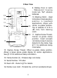
2 Front View 4 3 5 6 7 2 8 1. Keypad - Power, Accuracy, Units, and Volume switches. Refer to §5 & 6 for detailed operation. 2. LED's - Easy to see Light Emitting Diodes show position of laserometer relative to the laser beam. Green for on-grade and Red for high or low. 3. Beeper output - Fast audible signal is too High; lower to get to on-grade. Solid signal is On-grade. Slow signal is too Low; raise to get to on-grade. 1 4. Bubble Vial - aids in keeping laserometer level for accurate readings. 5.
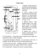
3 Rear View 14 13 12 11 10 15 16 9 9. Battery Door & Latch - Waterproof housing holds two "AA" alkaline batteries. 10. Marking Notch - Used to transfer or mark elevation position in handheld applications. Aligns with center on-grade position. Top of detector is 3.15 in (80 mm) from marking notch. 11. Captive Screw Thread, Center on-grade clamp position. Insert accepts rod clamp screw to secure detector to the clamp. See §7.11 for additional clamp information. 12.
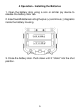
4 Operation - Installing the Batteries 1. Open the battery door using a coin or similar pry device to release the battery door tab. 2. Insert two AA batteries noting the plus (+) and minus (-) diagrams inside the battery housing. 3. Close the battery door. Push down until it "clicks" into the shut position.
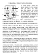
5 Operation - Primary Switch Functions 1 2 1. Power Switch - Press the power switch to turn power ON. All LED's, the LCD, and the beeper will come on momentarily. CAL will be displayed and LED's sequenced as the unit goes through a self-calibrating procedure for approximately 3 seconds. 4 3 NOTE: Do not power up the unit in a laser beam or strobe. If detected, the unit will revert to the previous calibration. Press and hold the Power switch for 2 seconds to turn power OFF. 2.
6 Operation - Secondary Switch Functions 7 6a 6 6c 6b 5 5. LED Display - Pressing the Units and Volume switches together enables the selection of LED's ON Bright, ON Dim, or OFF. Press together to cycle the selection. The LED's will display the current level of brightness selected as the switches are pressed. The LED light bulb symbol on the LCD will also change to display the selected setting. 6. Menu - Pressing the Accuracy and Volume switches together enables entry into the Menu functions.
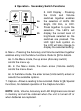
7 Liquid Crystal Display 7 8 9 6 5 10 4 11 3 12 2 1. Grade indication arrows 2. Battery status indicator 3. Laser out-of-level / laser low battery indicator 4. LED brightness level 5. Beeper volume level 6. Auto shut-off timer 7. Units of measure 8. Numeric elevation / Menu text display 9. Numeric elevation for fractional inches / Menu text display 10. Accuracy (deadband) indicator 11. Offset on-grade clamp location 12. Center on-grade clamp location 1 1.
7 Liquid Crystal Display 2. Battery Status - indicates 4 levels of battery status. Full Batteries OK Half Initial Warning Outline - Approx. 30 Minutes Remaining Flashing Change Batteries 3. Laser Out-of-Level and Laser Low Battery warning - certain laser transmitters can signal warnings by changing the rotation speed (RPM) of the laser. When enabled, the transmitter outline is displayed with the appropriate out-of-level or low battery symbol.
7 Liquid Crystal Display 5. Beeper Volume - indicates if Loud, Medium, Low or Off is selected. No symbol represents beeper Off. Beeper Loud Beeper Medium Beeper Low 6. Automatic Shut-Off - clock symbol and number indicate a 30 minute (0.5 hour) or 24 hour shut-off is selected. No symbol indicates automatic shut-off is disabled. Refer to §9 for details. 30 minutes selected 24 hours selected 7.
7 Liquid Crystal Display 8. Numeric Elevation / Menu Text Display - when in the normal operating mode, the four-character graphic displays numeric elevation. Resolution and the decimal point will be determined by the units of measure and the accuracy selected. Refer to §11, Specifications, for details. Dashed lines across the display indicate the numeric vertical reception range has been exceeded. The numeric display may also be turned off. Refer to §9, Menu Functions, for details.
7 Liquid Crystal Display 10. Accuracy Indicator - indicates 5 levels of accuracy selections - Ultra Fine, Super Fine, Fine, Medium, and Coarse. Refer to §11, Specifications, for the specific values for each accuracy selected. No center bar is displayed for calibration mode. Refer to §8, Special Functions, for details. Ultra Fine Super Fine Fine Medium Coarse Calibration Mode 11. Offset on-grade clamp position - clamp position is sensed automatically and displayed.
8 Special Functions Capture Function: The Capture function is used to obtain a single reading and keep it displayed. This may be useful when the unit may not be visible and grade information needs to be obtained. When in the laser beam and power on, momentarily press the Power/Capture switch. The current elevation reading will be saved. A flashing display will confirm the reading has been captured. Press any switch to return to normal operation.
9 Menu Functions The Menu screen is accessed by pressing the Accuracy and Beeper switches together for approximately two seconds. Menu text will appear in the numeric display area. The first line is the menu function. The second line is the current setting for that function. The remainder of the LCD will be clear. No elevation information will be displayed while in the menu screens. Menu items are selected by scrolling up or down the blue scroll arrows (▲▼) on the Accuracy and Volume switches.
9 Menu Functions AVG - Numeric & Arrow Averaging - HI / MD / LO - Averages laser beam strikes to improve arrow display performance at long distances. Algorithm factors in laser RPM and accuracy setting. MD is default setting and used for most applications. HI can be used in windy conditions, when the laser beam may be unstable, or when working at long distances. NOTE: Refer to the laser's specifications for accuracy and distance information. LO uses minimum averaging to display laser strikes. D.R.O.
9 Menu Functions GRD.A. - Grade Alarm - ON / OF - Special application function that when turned ON, disables the audible signal when ongrade. When moved out of the on-grade deadband, the beeper activates as normal. Default is OF. A.S.O. - Automatic Shutoff - 0.5 / OF / 24 - Selects automatic shutoff time from last laser strike. Default is 30 minutes. 0.5 - 30 minute shutoff. OF - Automatic shutoff turned Off. 24 - 24 hour shutoff. TX.O.L. - Transmitter Out-of-Level - OF / 6.7 / 5.0 / 3.3 / 2.7 / 2.
10 Rod Clamp 6 1 5 2 4 3 1. Captive Rod Clamp Screw - attaches to the back of detector. 2. Alignment Points (2) - help secure and align rod clamp. 3. Clamping Screw Knob - secures clamp to rods by moving the traveling jaw. Clockwise tightens; Counterclockwise loosens. 4. Reference Bar - top of bar is aligned with the detector's ongrade location for both standard center on-grade and offset on-grade clamp locations. 5. Traveling Jaw - moving jaw grips tightly to rods. 6.
11 Specifications Working Radius: 3 ft. - 1000 ft. (1 m - 300 m) Laser dependent Laser Detection Height: 5" (127 mm) Numeric Readout Height: 4" (102 mm) Accuracy: In In (frac) ft mm cm Ultra Fine 0.02 1/32 0.002 0.5 0.05 Super Fine 0.05 1/16 0.005 1.0 0.10 Fine 0.10 1/8 0.010 2.0 0.20 Medium 0.20 1/4 0.020 5.0 0.50 Coarse 0.50 1/2 0.050 10.0 1.0 Calibration 0.01 1/64 0.001 0.1 0.
12 Warranty Apache Technologies, Inc. STORM laserometer and clamp are warranted to be free of defects in material and workmanship for a period of three years. This warranty period is thirty-six months from the date the product is delivered from the dealer to the purchaser or is put into service by a dealer as a demonstration unit or rental unit.
13 Maintenance and Safety Detector Cleaning: Do not wipe dust or dirt off the detector reception window or display windows with a dry cloth or other abrasive material as scratching could occur, reducing visibility through these windows. A soft cloth and mild soap and water are effective. The unit may be submerged under water or sprayed with a low pressure hose if necessary. Do not use any other fluids other than water as they may attack polymer components.
CE DECLARATION OF CONFORMITY Application of Council Directive: 89/336/EEC Manufacturer's Name: Apache Technologies, Inc. Manufacturer's Address: 8261 State Route 235 Dayton, OH 45424 USA European Representative Address: Apache Technologies Europe GmbH Langenberger Str.
8261 State Route 235 Dayton, OH 45424 USA Phone: (937) 482-0200 Fax: (937) 482-0030 www.apache-laser.