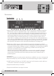
MANUAL CHAMP-3D Audiophile Digital Power Amplifier INFO@APART-AUDIO.
Safety first! •C aution: hot and sharp surfaces! This professional device needs to be installed by qualified personnel only. • Please check the packing for any kind of damage upon reception of the goods. If the packing is damaged, please contact your dealer before opening it. • !!!! Danger!!!! Exposure to high sound pressure levels may cause permanent hearing loss.
Features •M odular design, high power 2.1 amplifier with 3 Hypex™ audiophile Class-D digital amplifier modules. • High end operational amplifiers in the analog signal path. • High thermal efficiency, typically 92%. • Exceptionally high damping factor for tight bass response. All the benefits of a Class-D amplifier with the highly appreciated classic analog amplifier sound. • Design without fans, oversized convectional cooling, traditional power supply unit.
Connections Rear panel layout 1 4 5 6 2 7 3 8 9 10 11 12 13 14 15 1) External volume control on 2 pole euroblock : here you can connect a standard 10 kΩ linear potentiometer, wired as an adjustable resistor, using a shielded cable. Connect the shield to the – connector. When enabled in the settings menu, this external potentiometer allows you to increase or decrease the master volume in 2 dB steps.
6) Right channel balanced input on euroblock. Items 4, 5 and 6 are hardwired internally and can be used to create a daisy chain for connecting even more amplifiers. 7) Left channel balanced input on euroblock. Items 7, 8 and 9 are hardwired internally and can be used to create a daisy chain for connecting even more amplifiers. 8) Left channel XLR male input signal connector. 9) Left channel XLR female input connector. 10) Subwoofer output on 4 pole Speakon® connector.
Operation Front panel layout 1 2 3 4 5 6 7 8 1) Power switch: power on the unit by flipping the switch to the ‘on’ position. In the ‘OFF’ position, ALL electrical circuits are disabled. In the ‘on’ position, the unit can be switched to standby using an RS232 instruction, which will turn off the main power supply, resulting in very low standby power consumption. 2) Sub mute/select switch: during normal operation, push once to mute the sub channel.
) Rotary encoder: in normal operation, you can control the master volume with this encoder. When you enter the menu, this encoder is used to change the selected parameter value. The editable parameter will be highlighted in the display. 8) Standby LED: this LED lights up when the amplifier is in standby mode. The standby function is available via RS232 instruction only. When the mains power switch is in the OFF position, all electrical circuits will be deactivated and standby mode will not be available.
You will notice that an up - and down arrow has appeared next to the push buttons. Use these to scroll through the different menus. When you want to enter a menu - in this case the “LEVELS” menu is highlighted - push the upper button. The next screen appears. Now use the up - or down buttons to select the SUB, LEFT or RIGHT channel and turn the rotary encoder to set the level.
LEVELS MAX LEVELS Here you can edit the levels of all channels relative to each other. Default value is 0 dB. It is recommended to use this parameter for level matching only. Example: you want to adjust the level of the subwoofer because it is 3 dB louder than the L/R speakers: in this case set the SUB parameter to -3 dB. After adjusting, push the upper button to go back to the main menu, select “SAVE AND EXIT” and push the upper button again to save your selection.
CROSS-OVER Top type means: crossover type for the L/R channels. This parameter is linked for both channels. Sub type means: crossover type for the Sub channels There are different types of crossover characteristic selectable: OFF -> no crossover, the channels work at full range, valid for L/R amplifiers only.
Peaking equalizer: The line at the top shows a peaking equalizer with a relatively low Q-factor or wide bandwidth. Boost level is 9dB, center frequency is 1 kHz. This type of equalizer corresponds to the typical mid-tone control found on most audio equipment. Red line shows a peaking equalizer with a rather high Q-factor or low bandwidth, Cut level is -6dB. Center frequency is 100 Hz. Lo and Hi shelf equalizer: The line at the top shows a high shelf equalizer, the red line shows a low shelf equalizer.
DELAY DELAY menu: The delay can be adjusted in steps of 291.6667 µs, which is the time necessary for sound to travel 10 cm in dry air at 20°C. For convenience, the delay time is expressed in meters, not in µs. The delay menu contains the following submenus: LEFT DELAY: set the delay from 0 to 6 meters in 0.1 meter steps for the left channel RIGHT DELAY: set the delay from 0 to 6 meters in 0.1 meter steps for the left channel 0 meters corresponds to 0 milliseconds, or no delay (OFF).
EXT VOL potmeter connection, use a standard shielded audio cable: CONNECT TO EXT VOL CONTROL CONNECT TO EXT VOL CONTROL + EXIT Exit the main menu and return to the main screen without saving. Please note that some parameters, such as system settings will automatically be saved. SAVE AND EXIT Exit the main menu and save all parameters that have been changed.
!!!IMPORTANT!!! When the command (SET, GET, INC, DEC) is invalid, the unit will send: “ERROR: Unknown Command!” When an invalid attribute is sent, the unit will reply: “ERROR: Unknown Attribute!” When you attempt to send an instruction with a value out of range, the unit will reply: “ERROR: Value Invalid!” However, this does not apply to output level related commands. In these cases, the unit will set the value to the value closest to the absolute limit value. For example, you send “SET MASTER -99”.
Each instruction has at least a command and an attribute. In many cases, extra values are necessary, such as a numeric or binary value. Instructions always have to be ended with , carriage return. No space between the last character of the instruction and the . Instructions are not case sensitive! The 4 possible commands are: SET, GET, INC and DEC. With the INC and DEC command, a “step value” can be specified. This needs to be a positive number between 1 and 10.
MAXMASTER: set this parameter to the desired maximum master level. If set to a value of -20, the maximum possible level is -20 dB. If the user wants to abuse this setting and increases the level at the input, the amplifier will start to reduce the internal gain. The VU meter level LED’s will change from green to orange, indicating that the gain is being reduced. In worst case, the amplifier will show “INPUT OVERLOAD” on the display, and the lower LED’s on the VU meters will blink red.
parameter to OFF. Changes will be displayed only when EQ is set to ON. EQTYPE: possible commands: GET, SET. You have to specify the equalizer band from 1 to 4. Possible values are OFF, HPF, LOSHELF, PEAK, HISHELF, LPF. A command could look like this: “GET EQTYPE 3”. The unit will reply: “EQTYPE 3 PEAK” indicating that the third band of the equalizer is a peaking type equalizer. EQFREQ: possible commands: GET, SET. You have to specify the equalizer band from 1 to 4. Possible values are from 10 to 20000.
STORE: possible commands: GET, SET. Binary value is ON only. Use this command to store all edited audio related parameters. The store instruction looks like this: “SET STORE ON”. ECHO: possible commands: GET, SET. Binary values are ON, OFF. Use this command to enable or disable ECHO via RS232. LF: possible commands: GET, SET. Binary values are ON, OFF. Use this instruction to enable or disable Line Feed via RS232. BS: possible commands: GET, SET. Binary values are ON, OFF.
RS232LOCK: possible commands: SET. Binary value ON or OFF. With the command: “SET RS232LOCK ON” you can lock operation via RS232. The RS232 lock function will be active ONLY WHEN THE (front panel) LOCKMODE IS SET TO LOCKED OR VOL ONLY! When lock mode is set to LOCKED or VOL ONLY, it is not possible to unlock the RS232 lock using an RS232 command! First unlock the unit using the front panel controls -> RS232 lock will automatically be unlocked.
Warning and error messages shown on the LCD display • SUB AMP SHUT DOWN: the subwoofer amplifier has shut down due to an error: overtemperature, supply voltage error or short circuit on the output. • SUB AMP DC ERROR: the subwoofer amplifier has encountered a DC offset error and has shut down. • LEFT AMP SHUT DOWN: the left channel amplifier has shut down due to an error: supply voltage error or short circuit on the output.
!!!IMPORTANT!!! This amplifier relies on convectional cooling only. In normal situations, overheating will not occur. Since there are no noisy cooling fans in the amplifier, make sure the convectional cooling system can work properly. The unit can be built in a 19 inch rack system, but it is forbidden to block the ventilation openings at the front, rear, top and bottom. Therefore, it is absolutely necessary to allow at least one free rack space or 44 mm above and beneath the amplifier.
Technical specifications Dynamic program power per channel left/right amp 370W @ 4Ω , 530W @ 2.7Ω Sine wave power per channel left/right amp 350W @ 4Ω Dynamic program power subwoofer channel 1350W @ 2Ω Sine wave power subwoofer channel 1100W @ 2Ω Load impedance left/right amp 2.
Protection circuits overcurrent, overtemperature, DC offset, AC and DC over- and undervoltage Channel separation >80dB @ 1kHz Damping factor > 400 all channels APC sytem internal compressor and clip limiter, auto gain circuit Power amp topology class D Cooling convectional External interface RS232 and external volume control 0-10V (1 mA closed loop circuit) RS232 settings 19200 baudrate, 8 databits, no parity, no handshake Max power consumption 1500W Standby power consumption <1.
ANY SUGGESTION? They are well appreciated and eventually rewarded! Send your ideas or suggestions to suggestions@apart-audio.com Company names, product names, and names of formats etc. are the trademarks or registered trademarks of their respective owners. © 2011 APart-Audio specifications subject to change without notice. CHAMP-3D is developed by Audioprof nv Industriepark Brechtsebaan 8 bus 1 BE-2900 Schoten BELGIUM 24 WWW.APART-AUDIO.