Symmetra PX 10-80 kW 208 V Site Preparation Guide
Symmetra® PX 10-80 kW 208V Site Preparation Guide Sym metra® Quick -Start User PX Guide
Contents IMPORTANT SAFETY INSTRUCTIONS . . . . . . . . . . . . . . . . . . . . . 1 SAVE THESE INSTRUCTIONS . . . . . . . . . . . . . . . . . . . . . . . . . . . 1 Symbols used in this guide . . . . . . . . . . . . . . . . . . . . . . . . . . . . 1 Overview of System Components . . . . . . . . . . . . . . . . . . . . . . . 2 Option: Symmetra PX 10-80 kW Battery Enclosure . . . . . . . . . . 2 Operating Environment . . . . . . . . . . . . . . . . . . . . . . . . . . . . . . 3 Space Considerations . . . . .
IMPORTANT SAFETY INSTRUCTIONS SAVE THESE INSTRUCTIONS This guide contains information on how to prepare the site for the installation of the UPS and optional equipment. Symbols used in this guide CAUTION! Read this important information to avoid equipment damage. Indicates that more information is available on the same subject in a different manual.
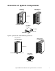
Overview of System Components UPS (Fully Loaded) 1166 lbs/529 kg UPS (Empty) 650 lbs/295 kg INTELLIGEN CE MODULE INTELLIGEN CE MODULE 82 in/2080 mm ? ? XR Communicati 36 in/915 mm DOC UME NT STO RAG E Sym Ba 10 sic - 40me Op kWtra era , ® PX tion200 GuV ide Sym Ba 10 sic - 40me Op kWtra era , ® PX tion200 GuV ide ons DOC UME NT STO RAG E 24 in/610 mm Power Module 60 lbs/26 kg 5.2 in/132 mm 19 in/483 mm 27.
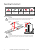
Operating Environment Install the UPS in an Indoor, Controlled Environment Temperature Range: 32°-104°F KeepVentilated Front-to-Rear Airflow Relative Humidity: <95% Non-condensing No Conductive Dust or Corrosive Fumes Max. Elevation: 10,000 ft. Full Load Heat Loss at Nominal Mains: 23,743 BTU/hr (6,957 Watts) Space Considerations CAUTION! If the UPS exceeds doorway height, remove from pallet and wheel through door (see Overview of System Components section for UPS height excluding pallet).
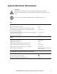
System Electrical Information CAUTION! All electrical power and power control wiring must be installed by a qualified electrician, and must comply with local and national regulations for maximum power rating. All current values are based on 80 kW maximum configuration of the UPS.
System Electrical Information Notes Recommended source connection. 1. Input electricity to be provided from a dedicated, grounded 4-wire Wye utility power source with a grounded neutral. 2. Ensure clockwise voltage phase rotation (L1,L2,L3). Recommended input protection (dual mains configuration). 3. Mains input: 350 Amp 3-Pole AC circuit breaker with 30 kAIC. 4. Bypass input: 300 Amp 3-pole AC circuit breaker with 30 kAIC.
System Electrical Information This UPS system has no built-in disconnection devices for AC output and DC input. An AC output over-current protection and AC output disconnect must be provided by the customer. For customersupplied external batteries, over-current protection and a disconnecting device for the battery circuits must also be provided by the customer. EPO switch wiring (required) The UPS is to be connected to either a dry contact or a 24Vdc Emergency Power Off (EPO) switch.
Basic Wiring Overview MBP (optional equipment) AC Power DC Power Interface wiring Battery Enclosure (Optional, 4 Max.
Site Preparation Checklist System Components. Have you – 5 5 verified that UPS output power meets current and future load (kW) requirements? added N+1 redundancy with an additional Power Module (Part # SYPM10KF). The UPS houses up to 9 power modules (up to 80 kW, N+1).
APC Worldwide Customer Support Customer support for this or any other APC product is available at no charge in any of the following ways: • Visit the APC Web site to access documents in the APC Knowledge Base and to submit customer support requests. – www.apc.com (Corporate Headquarters) Connect to localized APC Web sites for specific countries, each of which provides customer support information. – www.apc.com/support/ Global support searching APC Knowledge Base and using e-support.