Stationary Power Distribution Unit (SPDU) 3-phase, 75-300 kVA Installation Manual APC’s Stationary Power Distribution Unit (SPDU) was designed for application in various 3-phase environments. The SPDU can provide up to 11 sub-feed breakers, and offers the option of increasing the number of panel boards by adding side cars. Top and bottom cable entry is standard. Other features include total front accessibility, K1-K20 isolation transformers, and protective shielding.
SPDU Installation Manual
Contents Safety . . . . . . . . . . . . . . . . . . . . . . . . . . . . . . . . . . . . . . . . . . . . 1 Safety warnings . . . . . . . . . . . . . . . . . . . . . . . . . . . . . . . . . . . . 1 Live maintenance precautions . . . . . . . . . . . . . . . . . . . . . . . . . . 1 SPDU Overview . . . . . . . . . . . . . . . . . . . . . . . . . . . . . . . . . . . . 2 External components . . . . . . . . . . . . . . . . . . . . . . . . . . . . . . . . 2 Internal components . . . . . . . . . . . . . . . . . . .
Appendix B: Specifications/Data . . . . . . . . . . . . . . . . . . . . . . . 33 SPDU product specification . . . . . . . . . . . . . . . . . . . . . . . . . . . 33 SPDU with one sidecar . . . . . . . . . . . . . . . . . . . . . . . . . . . . . . 34 SPDU with two sidecars . . . . . . . . . . . . . . . . . . . . . . . . . . . . . . 35 Full load heat output (BTU/hr) . . . . . . . . . . . . . . . . . . . . . . . . . 36 Control fuses/supplementary protectors . . . . . . . . . . . . . . . . . .
Safety Safety warnings • ONLY QUALIFIED PERSONNEL are permitted to perform any task or function associated with the SPDU and its related equipment. Warning • This installation MUST COMPLY with the requirements of ANSI/NFPA 75 and NEC/NFPA 79 Art. 645. • All safety codes, safety standards, and/or regulations must be strictly observed during installation and ongoing maintenance of this equipment.
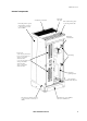
SPDU Overview External components Reset/silence push button Horn EPO (emergency power off) Monitoring screen and controls Upper panel board Main input circuit breaker Upper panel board breaker (225A) Hinged panels (4) Lower panel board breaker (225A) Lower panel board SPDU Installation Manual 2
SPDU Overview Internal components Ventilation for transformer Main cable entry plate Removable knockout plates for incoming branch cable Removable panel for 3-phase and neutral bus connections to sidecar (located on both sides of SPDU) Main input circuit breaker Provision for: a) Two 42-pole panel boards Cable clamps b) One 42-pole panel board and up to seven 225A sub-feed breakers c) One 42-pole panel board and up to three 400A sub-feed breakers d) Up to eleven 225A sub-feed breakers Equipment gro
SPDU Overview Custom configurations and options APC’s SPDUs are “built to order” as a means of satisfying each customer’s unique requirements. The customer is thus able to select an appropriate SPDU model, along with whatever features and options they would like to have incorporated into that model. Product SKUs. A total of 21 SPDU product SKUs are available.
SPDU Overview Dual-feed main breakers. The SPDU can be equipped with any of five types of dual-feed main breakers: • 225A (p/n PDCBRF225) • 400A (p/n PDCBRK400) • 600A (p/n PDCBRL600) • 800A (p/n PDCBRM800) • 1200A (p/n PDCBRN1200) Panel boards/sub-feed breakers.
SPDU Overview Floor jacks. A set of (four per unit) floor jacks (p/n PDFJ100) can optionally be applied to the SPDU (and its attached sidecar(s)) to provide leveling and/or additional clearance for bottom cable feed. The jacks are offered in heights of up to 18 inches, and are adjustable from one to three inches above the base. Refer to the installation steps below. Base Outline Threads into existing base Level nut Jam nut Floor pedestals available from 6.0 [15] X 12.0 [31] 6.
SPDU Overview Seismic bracing. Seismic bracing (p/n PDSB100) is optionally available as a means of securing the base frame of the SPDU (and sidecar) enclosure(s) to a concrete floor for those installations where additional stability is either required or desired. The diagram below shows the proper floor bracket placement and bolt locations for achieving seismic bracing on the 75-225[K13] kVA enclosure. Contact APC for hardware and torque specifications to meet various zone requirements.
SPDU Overview Monitoring. Three levels of SPDU monitoring are available: • Basic (p/n PDBMN100). Continuously monitors the temperature of the transformer, the status of the main input circuit breaker, and the status of a remote alarm contact. Local audio and visual alarms are initiated when the core temperature of the transformer exceeds maximum parameters. The main circuit breaker is then tripped or the remote alarm contact is closed. • Advanced (p/n PDAMN100).
Receiving and Transporting Shipping Each SPDU (with up to one sidecar attachment) is shipped on its own pallet. Additional sidecars are shipped two units to a pallet. For safety, pallets are slotted to allow forklift access from only one direction. The enclosures are likewise designed to accommodate forklift movement. To further stabilize the enclosures during shipping, (2) metal angle brackets connect the base of each unit to its pallet. Packaging materials are employed to minimize the effects of impact.
Receiving and Transporting Transporting Exercise caution. When transporting enclosures, try to avoid impact. Even the best packaging cannot guarantee equipment protection. In addition, keep personnel clear of an enclosure in transport. The units are heavy and can cause serious bodily injury. For size and weight information, refer to “Product SKUs” on page 4 or “SPDU with one sidecar” on page 34. Note Top box removal. Should the SPDU’s (and/or the sidecar’s) height exceed the doorway(s) by less than 5.
Installation Considerations Site requirements • The equipment should be kept in a climate-controlled environment with a temperature range of 0° to 40°C (32° to 104°F) and a relative humidity of 0% to 95%, non-condensing. • The equipment must be protected at all times from excessive moisture, construction dirt, corrosive elements, and other contaminants. • Make sure the floor’s surface is firm and level, and equipment does not exceed floor loading requirements.
Installation Considerations Clearances When placing the SPDU (and sidecars, if used) for installation, make certain each enclosure adheres to the following recommendations: • A FRONT clearance of at least thirty-six inches (36”) is recommended for front-access servicing. • A TOP clearance of at least eighteen inches (18”) supports ventilation.
Installation Considerations Placement Follow these instructions when placing enclosures: 1. Decide where the enclosure(s) will be placed and prepare the appropriate floor cutout(s), if necessary. Floor jacks or a full-frame floor stand (both are described on page 6) might optionally be used to attain recommended bottom clearance. The cutout for the 75-225[K13] kVA SPDUs is shown below. The cutout for the 225[K20] SPDU and the 300 kVA SPDUs is provided, as needed, with the Installation Drawings. 4.
Installation Considerations 6. Using a forklift, carefully lift the enclosure off its pallet and onto the floor. Now on casters, the unit can be rolled to its final position. Leveling feet (4 locations) BOTTOM of enclosure Removable connector plate - 32 x 1/2” conduit positions - 6 x 1/2-3/4” conduit positions Swivel casters (4 locations) Removable connector plate - 38 x 1/2” conduit positions - 6 x 1/2-3/4” conduit positions • Once the enclosure is on the floor, it may begin to roll.
SPDU Installation • Ensure that NO ELECTRICAL POWER SUPPLY is connected and that ALL BREAKERS are in the OFF position before installing the SPDU. • ALL WIRING INSTRUCTIONS must be followed precisely. Failure to comply could result in permanent damage to the equipment. Electrical Hazard Accessing the SPDU Front doors. • A handle mechanism interlocks the two front doors of the enclosure. Front door keys are tie-wrapped to the protective cover of the EPO button. To open the front doors: 1.
SPDU Installation • At the bottom of the SPDU are two (2) removable plates. These contain knockouts for connecting cables to the panel board and/or sub-feed breakers. Refer to “Internal components” on page 3 and the step 6 graphic on page 14. Power cables MUST NOT run near any control wiring. Leave a minimum 1” clearance between cables and wires. Caution • The final arrangement of knockouts will correspond to the customer’s chosen configuration. Removing trim.
SPDU Installation Wiring the SPDU Wiring considerations. • Because all electrical and mechanical connections can be accessed from the front of the SPDU, junction boxes are not required. A dedicated feeder should provide the necessary 3-phase input power to the unit.
SPDU Installation Units with transformers Input Input Main Suggested wire Input Main Suggested wire volts kVA FLA* breaker size (AWG) FLA* breaker size (AWG) 400 75 108 150A 1/0 108 150A 1/0 100 144 200A 3/0 144 200A 3/0 125 180 225A 4/0 180 225A 4/0 150 217 300A 350 MCM 217 300A 350 MCM 200 289 400A (2) 4/0 289 400A (2) 4/0 225 325 400A (2) 4/0 325 400A (2) 4/0 75 104 150A 1/0 104 150A 1/0 100 139 175A 3/0 139 175A 3/0 125 174 225A
SPDU Installation Torque values. Because various types of breakers are used in these assemblies, consult the breaker nameplate for actual torque values based on wire sizes. • Main and sub-feed breakers (in-lbs): Wire size AWG No.
SPDU Installation Grounding electrode conductor (GEC). Prior to making any electrical wiring connections, a grounding electrode conductor (GEC) must be connected from the SPDU’s main ground busbar to the facility’s grounding electrode. NEC Table 250-66 provides recommended GEC sizing based on your SPDU’s operational capacity. While conduit is not a requirement, the GEC connection must be protected from damage. A cable tray, raceway, or cable sheath are alternative safeguards.
SPDU Installation SPDU (and sidecar) input connections. Input connections are made to the three termination points at the top of each input breaker (main circuit breaker, panel board breakers, and sub-feed breakers) in phase sequence A-B-C (L1, L2, L3). For those SPDUs equipped WITH a transformer, the main input feeder consists of the 3-phase conductors and one ground conductor (3W+G).
SPDU Installation SPDU (and sidecar) output connections. The following instructions for making output connections are applicable to the SPDU and each of its attached sidecars. 1. Install a distribution breaker a. Unlock and open the front door(s) of the enclosure. b. Open the hinged panel(s) to gain access to the panel boards. c.
SPDU Installation 3. Connect the cable to the distribution breaker The cable’s individual wires are connected to the distribution breaker’s bolt-on or snap-in position(s); the neutral bar, if necessary; and the ground bar. Torque to 25 in-lbs. – When connecting a 3-wire cable to a single-pole breaker: a. Connect the L1 wire (black) to the breaker’s one load-side termination point. b. Connect the Neutral wire (white) to any open termination point on one of the neutral bars.
SPDU Installation – When connecting a 4-wire cable to a triple-pole breaker: a. Connect the L1 wire (black), L2 wire (red), and Neutral wire (white) to the breaker’s three load-side termination points. b. There is no Neutral connection in this configuration. c. Connect the Ground wire (green) to any open termination point on one of the ground bars. These are the vertical bars located nearer to the panel boards. – When connecting a 5-wire cable to a triple-pole breaker: a.
SPDU Installation SPDU control wiring. The control wiring terminal block is located near the top frame of the SPDU, directly above the main input circuit breaker. Refer to the diagram below for the proper wiring termination points in the block. The recommended wire type is TEW/TW/MTW, with a size range of from #20-14 AWG. Strip enough insulation from each wire to achieve connection to the SPDU terminal block, then secure the wire with a small standard screwdriver. Torque to 4.5-6 in-lbs.
Sidecar Installation Sidecar characteristics The SPDU’s load distribution capability can be increased through the addition (attachment) of optionally ordered sidecars. At the customer’s discretion, each sidecar can be equipped with either one or two 42-pole panel boards. Sidecars can be connected (via busbar) to either side of the SPDU and daisy chained, if necessary. Like the SPDU, the sidecar offers top and bottom knockout plates to accommodate incoming cables.
Sidecar Installation Connecting sidecars to the SPDU General information. • When shipped mechanically assembled to the SPDU, the sidecar is already electrically connected (via busbar) as well. The busbar connections accommodate both power and ground. • When shipped separately, the sidecar contains splice kits and mounting hardware for connecting its busbar to the busbar in the SPDU. The following procedure describes how to connect a sidecar to the SPDU (WITH or WITHOUT transformer).
Sidecar Installation 2. Open the front door of the sidecar using the same procedure outlined in “Front doors” on page 15. Behind the front door is one large hinged panel that is opened by loosening its top and bottom turn screws. Retrieve the busbar splice plates and hardware inside the unit. 3. Using a Phillips screwdriver, remove a) the adjacent side panel on the SPDU; and b.) both side panels on the sidecar.
Sidecar Installation 11.Connect the ground busbar (refer to “Internal components” on page 3 and the step 8 graphic on page 28 for location of ground bus) using the (2) angled splice plates. Three 1/4 x 20 x 1” bolts are required. Torque to 6 ft-lbs. SPDU SIDECAR Cabinet walls Existing sidecar bus Existing SPDU bus Ground bus splice (C/W 5/16” hardware supplied) 12.Reinstall the sidecar’s external side panel.
Sidecar Installation Connecting sidecars to sidecars Electrical Hazard Ensure that NO ELECTRICAL POWER SUPPLY is connected to the SPDU, and that ALL BREAKERS in both units are in the OFF position. Step-by-step procedure. The procedure for connecting sidecars to sidecars (in a daisy chained alignment) is very similar to the procedure for connecting sidecars to the SPDU. Refer to the diagrams in the previous section for any visual support required. 1.
Appendix A: Electrical Checklist • ONLY QUALIFIED PERSONNEL are permitted to perform any task or function associated with this equipment! Electrical Hazard • Ensure that NO ELECTRICAL POWER SUPPLY is connected and that ALL BREAKERS are in the OFF position before installing or servicing the SPDU! 1. Confirm that clearances for cabling, service access and ventilation correspond to specifications. There should be a minimum of 18” ABOVE the unit, 6” BELOW it, and 36” in FRONT. 2.
Appendix A: Electrical Checklist 13.Verify and record INPUT voltages on the main input circuit breaker. a. Volts, Phase A-B: b. Volts, Phase B-C: c. Volts, Phase C-A: d. Volts, Phase A-N: e. Volts, Phase B-N: f. Volts, Phase C-N: 14.If input voltage is incorrect, check for wiring errors or improper transformer tap upstream of the SPDU. 15.If main input breaker trips within (1) minute of turn on, contact APC Services or a factory rep for assistance.
Appendix B: Specifications/Data SPDU product specification Input Rated Power kVA: Output 75, 100, 125, 150, 200, 225, Nominal Output 300 Voltage: 208V/120V Nominal Input Voltage: 60 Hz @ 208V/480V/600V Distribution Panel (choice of): K Factor: K1, K13, K20 - One panel board and up to seven 225A sub-feed breakers Efficiency at Full Load: 96.
Appendix B: Specifications/Data SPDU with one sidecar Width 34 Depth Height Weight Product SKU IN CM IN CM IN CM LB KG PD75G6FK1 56 142 32 81 81.5 207 1790 812 PD75G6FK13 56 142 32 81 81.5 207 1840 835 PD75G6FK20 56 142 32 81 81.5 207 1860 844 PD100G6FK1 56 142 32 81 81.5 207 2045 928 PD100G6FK13 56 142 32 81 81.5 207 2070 939 PD100G6FK20 56 142 32 81 81.5 207 2215 1005 PD125G6FK1 56 142 32 81 81.
Appendix B: Specifications/Data SPDU with two sidecars Width Depth Height Weight Product SKU IN CM IN CM IN CM LB KG PD75G6FK1 76 193 32 81 81.5 207 2310 1048 PD75G6FK13 76 193 32 81 81.5 207 2360 1070 PD75G6FK20 76 193 32 81 81.5 207 2380 1080 PD100G6FK1 76 193 32 81 81.5 207 2565 1163 PD100G6FK13 76 193 32 81 81.5 207 2590 1175 PD100G6FK20 76 193 32 81 81.5 207 2735 1241 PD125G6FK1 76 193 32 81 81.
Appendix B: Specifications/Data Full load heat output (BTU/hr) Product SKU BTU/Hour kW PD75G6FK1 12276 3.60 PD75G6FK13 11253 3.30 PD75G6FK20 10912 3.20 PD100G6FK1 15004 4.40 PD100G6FK13 13640 4.00 PD100G6FK20 13129 3.85 PD125G6FK1 20631 6.05 PD125G6FK13 17732 5.20 PD125G6FK20 13299 3.90 PD150G6FK1 22506 6.60 PD150G6FK13 17391 5.10 PD150G6FK20 16368 4.80 PD200G6FK1 24723 7.25 PD200G6FK13 20290 5.95 PD200G6FK20 18926 5.55 PD225G6FK1 28133 8.
Appendix C: Monitoring Basic monitoring • The Basic monitoring package consists of an EPO Push button, a Horn, an Alarm Light, an Alarm Silence Push button, a Summary Alarm Relay, and Power Transformer High Temperature Thermostats (located in each coil). • The Power Transformer’s thermostat is set at 180°C. Should the Transformer reach or exceed this temperature, the Horn and Alarm Light become activated. The Summary Alarm Relay is also activated. • Depressing the Silence Push button silences the Horn.
Appendix D: Abbreviations and Acronyms 38 A: Amps AIC: Amps Interrupting Capacity ANSI: American National Standards Institute APC: American Power Conversion AWG: American Wire Gauge BTU: British Thermal Unit C: Centigrade CM: Centimeters C/W: Comes With D: Depth EPO: Emergency Power Off F: Fahrenheit FLA: Full Load Amps FT: Foot GEC: Grounding Electrode Conductor H: Height HZ: Hertz HVAC: Heating, Ventilation and Air Conditioning IEC: International Electrotechnical Com
SPDU Installation Manual 39
40 SPDU Installation Manual
SPDU Installation Manual 41
Life Support Policy/Warranty Life support policy American Power Conversion Corporation (APC) and its affiliates and subsidiaries worldwide do not recommend the use of any of their products in life-support applications where failure or malfunction of the APC product can be reasonably expected to cause failure of the life-support device or to significantly affect its safety or effectiveness. APC does not permit the use of any of its products in direct patient care.
Life Support Policy/Warranty Factory warranty APC warrants that the unit, when properly installed and commissioned by APC or APC authorized service personnel, shall be free from defects in materials and workmanship for a period of (1) year from the date of installation or maximum 18 months after manufacturing.
APC Worldwide Customer Support Customer support for this or any other APC product is available at no charge in any of the following ways: • Visit the APC Web site to access documents in the APC Knowledge Base and to submit customer support requests. – www.apc.com (Corporate Headquarters) Connect to localized APC Web sites for specific countries, each of which provides customer support information. – www.apc.com/support/ Global support searching APC Knowledge Base and using e-support.