
Installation manual


SPDU Installation
SPDU Installation Manual 21
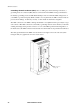
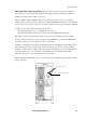
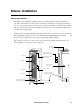
SPDU (and sidecar) input connections. Input connections are made to the three termination
points at the top of each input breaker (main circuit breaker, panel board breakers, and sub-feed
breakers) in phase sequence A-B-C (L1, L2, L3).
For those SPDUs equipped WITH a transformer, the main input feeder consists of the 3-phase
conductors and one ground conductor (3W+G). For SPDUs WITHOUT a transformer, the main input
feeder consists of the 3-phase conductors, one neutral conductor, and one ground conductor (4W+G).
Conductors to the main input circuit breaker should enter:
• through the main plate on top of the SPDU (for top entry), or
• through a removable connector plate at the bottom of the SPDU (for bottom entry).
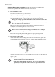
The A-B-C connections are made left-to-right to the positions shown in the graphic below. The
Ground connection (green) goes to the vertical bar on the FAR left side of the breaker. The Neutral
connection (white) goes to the vertical bar nearer to the breaker.
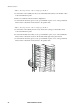
Conductors to the panel board and sub-feed breakers should enter through knockouts in the connector
plates at the bottom of the enclosure. Both of these breaker types have been rotated 90° counter
clockwise, and therefore the A-B-C connections on them are made from top-to-bottom. The Neutral
connection (white) goes to the vertical bar on the FAR left side of the breaker. The Ground
connection (green) goes to the vertical bar nearer to the breaker.
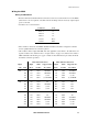
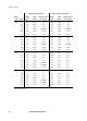
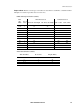
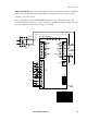
Refer to “Wiring considerations” on page 17 for conductor size, and then refer to appropriate “Torque
values” on page 19.
Main input circuit breaker
Input power connections
FRONT
FRONT