
Installation manual


SPDU Installation
22 SPDU Installation Manual
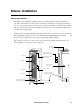
SPDU (and sidecar) output connections. The following instructions for making output
connections are applicable to the SPDU and each of its attached sidecars.
1. Install a distribution breaker
a. Unlock and open the front door(s) of the enclosure.
b. Open the hinged panel(s) to gain access to the panel boards.
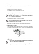
c. Select the next available breaker position(s) in either the upper or lower panel board, then
snap the new single-, double-, or triple-pole breaker into the appropriate guard rail.
d. Make bolt-on connections, if required (some breakers are simplified snap-in models,
negating the need for this step). Torque screws to 25 in-lbs.
e. Remove the corresponding plastic blanking plate on the appropriate hinged panel.
2. Install an output cable (or whip)
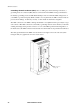
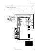
a. Attach a strain relief connector bushing to the cable as shown in the below graphic. Slide
enough cable through the strain relief connector to reach the intended distribution breaker.
b. Apply the strain relief connector to the next available knockout on the roof of the cabinet and
tighten in place.
Note
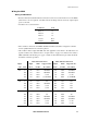
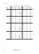
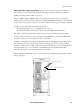
The top pole of a triple-pole breaker must always be placed in an L1 position on the
panel board. These are positions 1, 7, 13, 19, etc. on the left side and positions 2, 8,
14, 20, etc. on the right side of the board.
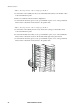
Note
There is one bolt-on connection for a single-pole breaker, two for a double-pole
breaker, and three for a triple-pole breaker.
Note
• To avoid cable congestion, start with the knockouts located toward the front
and center of the enclosure and work outward.
• If the cable is thicker than the standard 3/4” size, use a Greenlee punch (or
equivalent) to enlarge the size of the knockout. Use appropriate hardware.