Installation 150/175kW Modular PDU PDPM150G6F PDPM150L6F PDPM175G6H
Contents Overview .......................................................................... 1 Important Safety Information . . . . . . . . . . . . . . . . . . . . . . . . . . . . . . . . 1 Disclaimer . . . . . . . . . . . . . . . . . . . . . . . . . . . . . . . . . . . . . . . . . . . . . . . 2 Please Note: . . . . . . . . . . . . . . . . . . . . . . . . . . . . . . . . . . . . . . . . . . . . 2 Additional Safety Information . . . . . . . . . . . . . . . . . . . . . . . . . . . . . . .
Power Distribution Modules (PDMs). . . . . . . . . . . . . . . . . . . . . . . . . 14 Installation . . . . . . . . . . . . . . . . . . . . . . . . . . . . . . . . . . . . . . . . . . . . . 14 Remove power distribution modules (PDMs) . . . . . . . . . . . . . . . . . 15 Install filler plates . . . . . . . . . . . . . . . . . . . . . . . . . . . . . . . . . . . . . . . 15 Options ........................................................................... 16 Shielding Troughs . . . . . . . . . . . . . . . . .
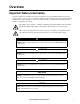
Overview Important Safety Information Read the instructions carefully and look at the equipment to become familiar with the device before trying to install, operate, service or maintain it. The following special messages may appear throughout this manual or on the equipment to warn of potential hazards or to call attention to information that clarifies or simplifies a procedure.
Disclaimer The information presented in this manual is not warranted by Schneider Electric to be authoritative, error free, or complete. This publication is not meant to be a substitute for a detailed operational and site specific development plan. Therefore, Schneider Electric assumes no liability for damages, violations of codes, improper installation, or any other problems that could arise based on the use of this publication.
Additional Safety Information Before you begin Verify that the system is free from all short circuits and grounds, except those grounds installed according to local regulations (according to the National Electrical Code in the U.S.A., for instance). If high-potential voltage testing is necessary, follow recommendations in equipment documentation to prevent accidental equipment damage. Before energizing equipment: • Remove tools, meters, and debris from equipment. • Close the equipment enclosure door.
About This Manual This manual is intended for users of the specified APC equipment. It contains important safety warnings and instructions, gives an introduction to the display interface and provides detailed information for proper use of the equipment. Related Documents Download technical publications and other technical information or look for updates to your manual at our website at www.apc.com.
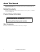
Installation Electrical Safety SAVE THESE INSTRUCTIONS! This document contains important instructions that should be followed during installation of the 150/ 175kW Modular Power Distribution Unit (PDU). DANGER HAZARD OF ELECTRIC SHOCK • Only certified electricians are authorized to connect power to the PDU. • The PDU must be installed in accordance with the National Electrical Code or the Canadian Electrical Code and all applicable local codes.
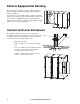
Proper bonding is essential to create an equipotential plane between service grounds and equipment during fault and transient conditions. Connect the two equipotential bonding conductors between adjacent enclosures in the system. The bonding conductors are pre-connected to the PDU. The M8 nuts and washers are supplied in the accessory kit. Move the equipotential bonding wires to fit your system configuration.
Install Input Power Cables Top entry installation 1 Open the front door. Unlatch and swing the display interface and bracket out towards the front door. 2 Loosen the captive screws and remove the top safety panel. 3 1 2 pdx0830a 3 Loosen the captive screws and remove the front top plate. 4 Remove the dedicated cover plate. Drill holes in the plate for conduits and re-install the plate with the conduits installed. 4 5 For PDPM150G6F and PDPM175G6H: L1, L2, L3 - Torque: 31.1 Nm (275 lb-in).
Bottom entry installation Note: The sidecar is required for undefloor wiring into the PDU. The Sidecar does not contain a switch or circuit breaker so a readily accessible disconnect device shall be incorporated external to the equipment. Sidecar Model PDPM150SC PDU Model PDPM150G6F PDPM150L6F PDPM175G6H PDPM100SC 1 Remove the dedicated cover plate. Drill holes in the plate for conduits and re-install the plate with the conduits installed.
3 Take the cables that are preinstalled in the Side Car and route them through the left side into the PDU.
Install Subfeed Cables 1 Open the rear doors. 1 2 pdx0823a 2 Remove the subfeed safety panel. 3 Loosen the four captive screws on each of two rear dedicated cover plates. Drill holes in the plates for conduits and re-install the plate with the conduits installed. 3 pdx0829a Note: Remove cover plates before cutting holes. 4 Connect the phase (L1, L2, L3) cables. Torque: 31.1 Nm (275 lb-in). 5 Connect the neutral (N) cable. Torque: 62.2 Nm (550 lb-in). G N 6 6 Connect the ground (G) cable.
Install User Input/Output Contacts Note: Contact wires from external signaling, alarming, and sensing devices may be connected to the interface board to allow the controller to monitor these devices and to also control outside devices through the output contacts. 1 Open the front door and remove the top safety panel. 1 2 pdx0826a 2 Note the location of the interface board at the top of the PDU. 3 Loosen the captive screws and remove the plate. Remove the 3/4-in (64-mm) knockout.
5 Make connections to the labelled terminals on the interface board. Note: Input Contacts are Normally open or Normally closed. Available Output Contacts: DPDT, 1A@30VDC AST0, AST1, AST2, ASTEN, AC/DC, +24V, and EPO CONTACT are reserved and not available. Wiring: 12 AWG to 30 AWG is recommended.
Install the Communication Cable 1 Connect the CAT-5 cable for StruxureWare Central or your local area network to the RJ45 connection coupling on top of the PDU. 1 3 The other end of the internal cable is plugged into the RJ-45 port on the panel cover of the controller located at the bottom of the unit. 150/175kw Modular PDU Installation pdx0837a 2 pdx0838a 2 Inside the PDU enclosure, a second CAT5 cable is connected to the other side of RJ45 coupling.
Power Distribution Modules (PDMs) Installation Note: 1. Power distribution modules can be safely installed when the PDU is operational. 2. Install only APC-supplied PDMs with matching output voltage. 3. Install PDMs starting from the bottom of the panel to avoid cable congestion. 1 Open the front door of the PDU. pdx0797a 1 2 Remove the filler plates. Press down on the filler plate clip to release its locking mechanism.
6 Slide the PDM into the panel using the top and bottom guide tracks for that position. Make sure you slide the PDM all the way into its position. 7 Close the latch. This will tighten electrical contacts in the PDM against the busbar. 6 6 6 pdx0298b 8 Feed cable from the PDM through the slot in the roof of the PDU. Note: Leave a minimum of 7 inches (178 mm) of slack in the cable behind the module. The slack is useful in case the module is ever removed or replaced.
Options Shielding Troughs pdx0844a 1 1 Snap an APC-provided trough into slots on the roof of the PDU. The tabs at the base of the trough must fit securely into the slots. Note: Properly align the PDU trough with troughs installed on top of the enclosures located adjacent to the PDU. pdx0845a 2 2 Feed PDM cables through the roof of the PDU and into the trough system for connection with the appropriate rack-mount PDUs.
Seismic Stability Kit Install rear anchoring brackets 1 Secure the floor anchoring bracket to the floor using floor anchoring bolts (not supplied). Use M12 strength class 8.8 or 1/2 inch, grade 5 steel bolts. 1 2 Secure the back of the other half of the bracket assembly to the back of the unit. 2 3 Push the unit back to slide the bracket on the unit under the bracket bolted to the floor.
Install front anchoring bracket 1 Secure the front anchoring bracket to the enclosure. 1 2 Secure the front anchoring bracket to the floor using floor anchoring bolts (not supplied). Use M12 strength class 8.8 or 1/2 inch, grade 5 steel bolts.
Specifications AC Input Model PDPM150G6F PDPM150L6F PDPM175G6H Nominal voltage 480V, 3W +G 600V, 3W +G 480V, 3W + G Frequency 60 Hz 60 Hz 60 Hz Maximum continuous current 180 A 150 A 214 A Nominal current 178 A 141 A 214 A Recommended current rating of input circuit breakers Mains Input1 (A) 225 200 300 2000 1500 2100 Inrush currents Inrush Current2 Standard circuit breakers are rated to carry 80% of their current rating continuously.
Distribution Transformer PDPM150G6F PDPM150L6F PDPM175G6H Size 150 kVA 150 kVA 175 kVA Type Delta/Wye Delta/Wye Delta/Wye Input voltage 480V 600V 480V Input current 180 A 150 A 214 A Output voltage 208Y/120V 208Y/120V 415Y/240V Output current 399.72 A 399.72 A 243.47 180 NC 180 NC 180 NC 455 kg (1003 lb) 500 kg (1102 lb) 560 kg (1235 lb) Efficiency 98.2% min. 98.2% min. 98.5% min.
Recommended conductor sizes Note: All wiring must comply with all applicable national and or local electrical codes.
Table for 30°C ambient/4CCC PDPM150G6F 480:208 PDPM150L6F 600:208 PDPM175G6H 480:415 Mains Input Φ Cu: 4/0 AWG A1: 300kcmil 75°C conductor minimum Cu only: 3/0 AWG 90°C conductor minimum Cu: 300kcmil Al: 400kcmil 75°C conductor minimum Equipment Grounding Conductor (EGC) Cu: 4 AWG A1: 2 AWG Cu: 6 AWG Cu: 4 AWG Al: 2 AWG Grounding Electrode Conductor (GEC) Cu: 2 AWG A1: 1/0 AWG Cu: 2 AWG Cu: 2 AWG Al: 1/0 AWG Output Supplied with Power Distribution Modules Subfeed Output Cu: (2) 250kcmil Φ
Radio Frequency Interference Note: Changes or modifications to this unit not expressly approved by the party responsible for compliance could void the user’s authority to operate this equipment. USA—FCC This equipment has been tested and found to comply with the limits for a Class A digital device, pursuant to part 15 of the FCC Rules. These limits are designed to provide reasonable protection against harmful interference when the equipment is operated in a commercial environment.
APC Worldwide Customer Support Customer support for this or any other APC product is available at no charge in any of the following ways: • Visit the APC Web site to access documents in the APC Knowledge Base and to submit customer support requests. – www.apc.com (Corporate Headquarters) Connect to localized APC Web sites for specific countries, each of which provides customer support information. – www.apc.com/support/ Global support searching APC Knowledge Base and using e-support.