InfraStruXure™ for Wiring Closets and Computer Rooms: Site Preparation, Site Planning, and Installation InfraStruXure for Wiring Closets and Computer rooms is an integrated power, rack, air, and management architecture consisting of standard, plug-and-play components. This architecture allows for fast and easy installation, and helps eliminate disorganization within an IT environment by providing a foundation for your critical IT equipment that fosters organization, ease-of-use, and control.
This manual is available in English on the enclosed CD. Dieses Handbuch ist in Deutsch auf der beiliegenden CD-ROM verfügbar. Este manual está disponible en español en el CD-ROM adjunto. Ce manuel est disponible en français sur le CD-ROM ci-inclus. Questo manuale è disponibile in italiano nel CD-ROM allegato. Deze handleiding staat in het Nederlands op de bijgevoegde cd. Instrukcja Obslugi w języku polskim jest dostępna na CD. O manual em Português está disponível no CD-ROM em anexo.
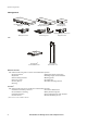
System Components Rack NetShelter VX® Enclosure NetShelter VX Open Frame NetShelter 4-Post Open Frame NetShelter 2-Post Open Frame Power Smart-UPS® 1500 VA, 2200 VA 3000 VA, 5000 VA Smart-UPS RT 2000 VA, 3000 VA 5000 VA, 7500 VA, 10,000 VA Symmetra® RM 2–6 kVA Symmetra LX 4–8 kVA, 8–16 kVA Power Distribution Basic Rack PDUs Metered Rack PDUs Switched Rack PDUs InfraStruXure for Wiring Closets and Computer Rooms 3
System Components Management InfraStruXure System Manager Environmental Management System Network Management Card Environmental Monitoring Card Environmental Monitoring Unit Building Management System Integration Card Air NetworkAIR® Air Distribution Unit NetworkAIR Air Removal Unit Rack accessories APC offers the following rack accessories for InfraStruXure Systems: • Stabilization plates and brackets • Keyboard drawers • Shielding troughs and cable ladders • Keyboards • Blanking panels • Rack-m
Site Preparation Verify the shipment Ensure that all labeled pallets and boxes match your purchase order. Do not unpack the pallets and boxes until you are ready to install the system. Environmental requirements Batteries can be permanently damaged if installed in a system that is not being used. Store battery modules at an ambient temperature below 25° C.
Site Preparation Access and ventilation requirements Consult your local and national building and fire codes for additional requirements. 457 mm 2527 mm 914 mm 914 mm Weight considerations Ensure that the floor and sub-floor can support the total weight of the system concentrated on the leveling feet of the system’s enclosure. If you are placing equipment on a raised floor, consult the flooring manufacturer for loading requirements before installing equipment.
Site Preparation Electrical requirements and safety Consult your UPS and power distribution manuals for detailed electrical requirements and installation instructions. Electrical Hazard Consult your national and local codes for requirements other than those listed in the manuals included with your products. The UPS contains internal batteries and may present a shock hazard even when disconnected from the branch circuit (mains). See the safety information in your UPS manual.
Site Preparation Electrical output 8 Voltages Supported Product Connection Type Symmetra RM 2–6kVA (8) IEC 320 C13 (2) IEC 320 C19 230 Symmetra LX 4–8kVA (8) IEC 320 C13 (6) IEC 320 C19 (1) Hard-wired 3-wire (G+N+L1) 230 Symmetra LX 8–16kVA (8) IEC 320 C13 (10) IEC 320 C19 (1) Hard-wired 3-wire (G+N+L1) 230 Smart-UPS 1500 (4) IEC 320 C13 230 Smart-UPS 2200 (8) IEC 320 C13 (1) IEC 320 C19 230 Smart-UPS 3000 (8) IEC 320 C13 (1) IEC 320 C19 230 Smart-UPS 5000 (8) IEC 320 C13 (2) IEC 32
Site Preparation Emergency Power-Off (EPO) Electrical Hazard A licensed electrician must connect the remote emergency power-off (EPO) device. If required by local or national codes, you must connect the EPO (to disable output power in an emergency) either as internally powered for use with non-powered switch circuits, or externally powered for use with +24 VDC-powered switch circuits.
Site Planning The following are sample configurations you can use to plan the layout of your computer room. Actual number of racks supported may be less than shown depending upon the actual load per rack.The clearances shown are the minimum requirements. Check your local and national codes for additional requirements. NetShelterVX Dimensions 1067 mm 600 mm Smart-UPS 1500 VA Supports up to two NetShelter VX enclosures and one UPS.
Site Planning Symmetra LX (4–8 kVA) Supports four NetShelter VX enclosures, one UPS, and one Rack PDU Extender. Parallel rows. Set up two short, parallel rows. Run a APC Cable Ladder between the rows. 914 mm UPS 914 mm PDU† 914 mm †Rack PDU Extender Adjacent short rows. Set up two short, adjacent rows. Run a APC Cable Ladder between the rows. 914 mm PDU† UPS 914 mm 1219 mm † Rack PDU Extender One row. Set up one long row.
Site Planning Symmetra LX (8–16 kVA) Supports eight NetShelter VX enclosures, one UPS, and one Rack PDU Extender. Parallel rows. Set up two short, parallel rows. Run a APC Cable Ladder between the rows. 914 mm UPS 914 mm PDU† 914 mm † Rack PDU Extender Adjacent short rows. Set up two short, adjacent rows. Run a APC Cable Ladder between the rows. 914 mm UPS PDU† 1219 mm †Rack 914 mm PDU Extender One row. Set up one long row.
Basic Installation Procedures Unpack racks and enclosures Unpack each rack and enclosure included with your shipment according to the unpacking instructions in the rack or enclosure manual. Make sure all boxes and packaging are empty before discarding them. Note Assemble racks and enclosures Orient the racks and enclosures in the planned location (see “Site Planning” on page 10), and make any necessary adjustments to the enclosures that are needed for your location.
Basic Installation Procedures 3. Level the enclosures. Leveling feet are attached under the enclosure at the corners. The leveling feet can help provide a stable base if the selected floor space is uneven, but cannot compensate for a badly sloped surface. To level the enclosure: a. Fit the 14-millimeter end of the open-ended wrench (provided) to the hex head just above the round pad on the bottom of a leveling foot.
Basic Installation Procedures Install Rack PDUs See the manual included with your Rack PDUs for detailed safety and installation instructions. See also Install vertical APC Rack PDUs in the rear of a NetShelter VX Enclosure, in the cable channel directly behind the rear vertical mounting rails. You can install the Rack PDU in one of two ways: using toolless mounting pegs (provided) or the mounting brackets (sold separately).
Basic Connection Procedures Overview This section illustrates typical configurations. Your configuration may vary. If you have questions, consult the user manual of each component, visit the APC Web site (www.apc.com), or contact Customer Support at a number on the back cover of this manual. Caution Do not use only these diagrams to connect your equipment. Read and follow the safety and connection instructions in the manual included with your UPS and power distribution equipment.
Basic Connection Procedures Symmetra RM 2–6 kVA UPS NetShelter VX Enclosure Input from Utility (L-N-G) Rack PDU (AP7852) Symmetra RM 2–6 kVA UPS Symmetra LX 8–16kVA UPS NetShelter VX Enclosure Input from Utility (L-N-G) Rack PDUs (AP7852) Symmetra LX 4–16 kVA UPS Rack PDU Extender InfraStruXure for Wiring Closets and Computer Rooms 17
Basic Connection Procedures Connect Rack PDUs to the UPS Route the Rack PDU power cords to the UPS through the bottom of the enclosures, using the holes in the enclosures’ vertical posts. Plug each power cord into an outlet on the UPS, or Rack PDU Extender. The diagram shows vertical Rack PDUs; however, you can use any APC Rack PDUs with plugs that match your UPS outlets, or Rack PDU Extender outlets. See “Electrical requirements and safety” on page 7 for information on the outlet type of each UPS.
Warranty InfraStruXure Standard Warranty APC warrants that all components of the InfraStruXure system will be free from defect in material and workmanship for a period of two years from the date of start up when start up has been performed by APC authorized service personnel*. If assembly services are included in the original purchase and are also performed by APC authorized service personnel, APC offers an additional year of warranty at no additional charge.
® APC Worldwide Customer Support Customer support for this or any other APC product is available at no charge in any of the following ways: • Visit the APC Web site to access documents in the APC Knowledge Base and to submit customer support requests. – www.apc.com (Corporate Headquarters) Connect to localized APC Web sites for specific countries, each of which provides customer support information. – www.apc.com/support/ Global support searching APC Knowledge Base and using e-support.