APC Smart-UPS Uninterruptible Power Supply Model 5000I User’s Manual 990-7032A, Revision 3 7/01
Entire contents copyright ©1999 by American Power Conversion. All rights reserved. Reproduction in whole or in part without permission is prohibited. Smart-UPS is a registered trademark of APC. All other trademarks are the property of their respective owners.
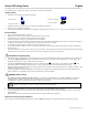
Smart UPS Safety Guide English This Safety Guide contains important instructions that should be followed during installation and maintenance of the APC equipment and batteries. It is intended for APC customers who setup, install, relocate, or maintain APC equipment. Handling Safety •= •= •= •= Be careful. Do not lift heavy loads without assistance. = <18 kg (<40 lb.) = 32-55 kg (70-120 lb.) = 18-32 kg (40-70 lb.) = >55 kg (>120 lb.
Table of Contents Introduction ................................................................................................................................................................................................1 Unpacking ..................................................................................................................................................................................................1 Installation.....................................................................
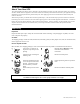
Introduction About Your New UPS This Uninterruptible Power Supply (UPS) is designed to prevent blackouts, brownouts, sags and surges from reaching your computer and other valuable electronic equipment. This UPS also filters out small utility line fluctuations and isolates your equipment from large disturbances by internally disconnecting from the utility line, while supplying power from its internal batteries until the utility line returns to safe levels.
Installation Installing your UPS requires six steps: 1. Position the UPS in the desired location. For rack mount units this may include installing the rails into the rack. 2. Hardwire the electrical connection on the input side (must be done by an authorized electrician). 3. Install the batteries. This 5000 VA UPS ships without the batteries installed. 4. Connect equipment to the UPS. 5. Power up the UPS. 6. Install PowerChute UPS monitoring software and accessories. 1.
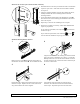
Determine the Location of the UPS in the Rack (continued) 1. Determine where in the rack you’ll mount the UPS. The SU5000 requires a space of 5U. Some racks have tick marks to indicate the U-spaces. 2. Using the mounting template provided (part number 990-0195), identify and mark the correct mounting holes for the UPS mounting brackets. 3. Locate and mark the bottom hole in the designated U-space . The bottom screw on the mounting rail will attach to the bottom hole in the U-space. 4.
The 5000 VA models (without batteries installed) require two people to lift due to their weight. Load the UPS into the Rack Supporting the UPS from the front and back, carefully align the unit with the rails. Slide the UPS into position. Attach the Mounting Brackets to the Rack Use the ornamental screws supplied with the UPS to attach the mounting brackets to the rack post. 2.
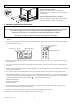
3. Install the Batteries The battery compartment is accessed from the front panel of the UPS. The 5000 VA unit requires four battery packs (each pack consists of four individual batteries). Note: Graphics are not drawn to scale. They are shown for reference only. 1. Remove the front bezel by grasping the finger clips on the side of the bezel and carefully loosening the four (4) snaps. 2. Use a screwdriver or coin to remove the two battery door screws and open the door. 3.
Initial Startup Rear Views 5000 VA Tower Model 5000 VA Rack Mount Model Charge the battery The UPS charges its battery whenever it is connected to utility power. The battery will charge fully during the first four hours of normal operation. Do not expect full runtime during this initial charge period. Connect Computer Interface Port (Optional) Power management software and interface kits can be used with this UPS. Use only kits supplied or approved by the manufacturer.
Low Battery Warning Interval By default, the low battery warning occurs when there are approximately two minutes of on-battery run time remaining. This may not be enough time to gracefully shut down some protected computer systems. To change the warning interval, press the rear panel configuration button while pressing and holding the front-panel on/test button. 2 min. The initial setting. 5 min. Press the configuration button once to set the low battery warning interval to approximately five minutes.
Operating Instructions Switch On — Switch Off With the UPS plugged in, press and release the large upper on/test button to supply power to the loads. The loads are immediately powered while the UPS beeps and performs a self-test. Press and release the small, lower off button to turn off power to the loads. It may be convenient to use the UPS as a master on/off switch for the protected equipment. Note: Whenever the UPS is plugged in and utility voltage is present, the charger maintains battery charge.
Load Bar Graph 85% 67% 50% 33% 17% The 5-LED display on the left of the front panel represents the power drawn from the UPS as a percentage of total capacity. For example, if three LEDs are lit, the load is drawing between 50% and 67% of the UPS’s capacity. If all five LEDs light, thoroughly test your complete system to make sure that the UPS will not become overloaded.
Replacing the Battery This UPS has an easy to replace hot-swappable battery. The battery compartment is located on the front panel for easy access. Battery replacement is a safe procedure, isolated from electrical hazards. You may leave the UPS and loads on for the following procedure. See your dealer or call the number in this manual for information on replacement battery cartridges. Note: Please read the cautions in Smart UPS Safety Guide, at the front of this manual.
User Configuration Items Function Automatic Self-Test Note: Setting these items requires optional software or hardware. Factory Default User Selectable Choices Description Every 14 days Every 7 days (168 hours), On Sets the interval at which the UPS will execute a self-test. (336 hours) Startup Only, No Self-Test UPS ID UPS_IDEN Up to eight characters to define the UPS. Use this field to uniquely identify the UPS for network management purposes.
Specifications Acceptable input voltage Output voltage Input protection Frequency limits (on-line operation) Transfer time Maximum load, total On-battery output voltage On-battery frequency On-battery waveshape Overload protection (on-battery) Noise filter Battery type Typical battery life Typical recharge time Operating temperature Storage temperature Operating and storage relative humidity Operating elevation Storage elevation Electromagnetic Compatibility (EMC) Electromagnetic Interference (EMI) Electrom
Regulatory Agency Approvals B N 394 ME 61 13 990-7032A, Revision 3 7/01
Troubleshooting Use the chart below to solve minor UPS installation problems. Contact APC Technical Support Staff for assistance with complex UPS problems. See APC Contact Information, page 15, for a location near you. Problem and Possible Cause UPS will not turn on. •=ON button not pushed. •=UPS not connected to AC power supply. •=UPS input circuit breaker tripped. •=Very low or no utility voltage. •=Battery not connected properly. UPS will not turn off. •=Internal UPS fault.
Service If the UPS requires service do not return it to the dealer! Follow these steps: 1. Review the problems discussed in Troubleshooting, page 14, to eliminate common problems. 2. Verify that no circuit breakers are tripped. A tripped circuit breaker is the most common UPS problem! 3. If the problem persists, call Customer Service or visit the APC Internet Website (www.apcc.com). •=Note the model number of the UPS, the serial number, and the date purchased.
Appendix A: Types of Racks and Mounting Hardware This appendix describes the hardware required for the different types of racks and describes the type of racks that may be used in your industry. All APC Rack Mount units are shipped ready for 19-inch wide EIA/IEC rack cabinets. Refer to the instructions included with the rails when mounting the UPS.
Appendix B: Transporting Your Smart-UPS Follow these guidelines if you need to ship the UPS to another location. These guidelines apply whether you are transporting the UPS alone, rack mounted in an equipment cabinet, or installed in a system. Caution: Always DISCONNECT THE BATTERIES before shipping the UPS to avoid damage during transport. (U.S. Federal Regulation requires that batteries be disconnected during shipment.) The batteries may remain in the UPS; they do not have to be removed.