C H A P T E R 2 Monitoring the System This chapter explains how to monitor the Cisco ICS 7750. The chapter is organized as follows: • Alarms, page 2-2 • Logging, page 2-3 • SNMP Basics, page 2-10 • Monitoring with ICS System Manager, page 2-16 • Monitoring with CiscoWorks2000, page 2-17 • Monitoring with Cisco IOS Software, page 2-18 • Monitoring a UPS, page 2-21 Cisco ICS 7750 Administration and Troubleshooting Guide 78-10169-02 Rev.
Chapter 2 Monitoring the System Alarms Alarms This section describes alarms, which indicate problems on the Cisco ICS 7750 or on systems with which it is communicating. Alarms are associated with the following: • Events—Physical problems, such as system overheating or loss of power, detected by the SAP card and reported to the ICS System Manager software.
Chapter 2 Monitoring the System Logging Alarm Levels The system has the following two alarm levels: • Major alarm (amber LED)—Any state that indicates a system malfunction that can immediately result in a service outage or that indicates a system problem that can seriously degrade service.
Chapter 2 Monitoring the System Logging Handling Log Messages with ICS System Manager ICS System Manager provides several options for handling the log messages directed to it. By default, the system sends log messages to the SPE, where they are stored on disk. ICS System Manager includes an Event Manager that enables you to view system events (messages) and define policies (a set of rules) that specify how you want the system to respond to a particular type of message.
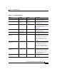
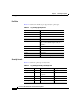
Chapter 2 Monitoring the System Logging Table 2-1 Log Message Elements Element Example Format Description Received date and time 1999 Nov 21 11:55:00 yyyy mmm dd hh:mm:ss The date and time when the message was received. Sent date and time 1999 Nov 21 11:55:00 yyyy mmm dd hh:mm:ss The date and time when the message was sent. FACILITY %LPR STRING Two or more uppercase letters that indicate the facility to which the message refers (see Table 2-2). From 192.31.7.19 n.n.n.
Chapter 2 Monitoring the System Logging Facilities Table 2-2 describes the facility types supported by log messages.
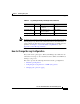
Chapter 2 Monitoring the System Logging Table 2-3 Note Log Message Severity Level Keywords (continued) Keyword Level Description Syslog Definition notification 5 Normal but significant LOG_NOTICE condition informational 6 Information—no action required LOG_INFO debugging 7 Debugging message LOG_DEBUG Not all messages indicate problems. Some messages are informational. Others may help diagnose problems with communications lines, internal hardware, or system software.
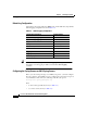
Chapter 2 Monitoring the System Logging Default Log Configuration System IOS components (ASI cards, MRP cards, and the SSP card) ship with the default logging configuration shown in Table 2-4.
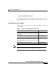
Chapter 2 Monitoring the System Logging • syslog path is the path to syslog.conf • myfile.log is the name of your log file The syslog daemon (syslogd) sends messages at the level specified in syslog.conf, provided that the file exists, and provided that syslogd has permission to write to it. Changing Syslog Server Logging To change syslog server logging behavior, use the global configuration commands shown in Table 2-5.
Chapter 2 Monitoring the System SNMP Basics SNMP Basics The Simple Network Management Protocol (SNMP) facilitates the exchange of management information among network devices. SNMP is part of the Transmission Control Protocol/Internet Protocol (TCP/IP) protocol suite. SNMP enables you to manage network performance, find and solve network problems, and plan for network growth.
Chapter 2 Monitoring the System SNMP Basics • An SNMP management application, together with the computer it runs on, is called a network management system (NMS). An NMS executes applications that monitor and control managed devices. NMSs provide the bulk of the processing and memory resources required for network management.
Chapter 2 Monitoring the System SNMP Basics The following system components, though not SNMP-managed devices, receive SNMP support through ICS System Manager: • System alarm processor (SAP) card • Power supply modules • Fans • Chassis SNMP Management Information Base A Management Information Base (MIB) is a collection of information that is organized hierarchically. MIBs are accessed using a network management protocol such as SNMP.
Chapter 2 Monitoring the System SNMP Basics On the Cisco ICS 7750, the ICS System Manager software (the NMS) typically sends SNMP requests to a single IP address to access the SNMP MIBs of any system component. The SNMP agent can then respond to MIB-related queries being sent by the NMS. Similarly, if CiscoWorks2000 is the NMS, it uses the MIB variables to set device variables and poll devices on the network.
Chapter 2 Monitoring the System SNMP Basics Supported MIBs The Cisco ICS 7750 supports the following MIBs: • CISCO-C2900-MIB—Supports the SSP card. • CISCO-CCM-MIB—Enables the system to get provisioning and statistical information about Cisco CallManager, devices associated with Cisco CallManager (such as Cisco IP phones and gateways), and the Cisco CallManager configuration.
Chapter 2 Monitoring the System SNMP Basics Cisco ICS 7750 Traps Cisco ICS 7750 ASI cards, MRP cards, and the SSP card can generate traps such as the following: • coldStart—Indicates power-up reset of a card. • warmStart—Indicates that software running on a card has been upgraded or that the card has been reset.
Chapter 2 Monitoring the System Monitoring with ICS System Manager • Note Number represents the target physical slot number (slots 1 through 8) of the SNMP request. All SNMP requests with a composite community string of @SLOT9 or higher are directed to the SSP, which determines the proper SNMP message destination.
Chapter 2 Monitoring the System Monitoring with CiscoWorks2000 Monitoring with CiscoWorks2000 CiscoWorks2000 uses SNMP to monitor and control system devices. You can integrate CiscoWorks2000 applications with other NMSs, such as HP OpenView. CiscoWorks2000 Applications CiscoWorks2000 applications extend industry-standard network management systems to facilitate checking the status of Cisco devices, maintaining device configurations and inventories, and troubleshooting device problems.
Chapter 2 Monitoring the System Monitoring with Cisco IOS Software SNMP and the CiscoWorks2000 Interface Using SNMP, CiscoWorks2000 retrieves CDP information by polling Cisco CallManager. After the discovery process is completed, a topology map reveals all the Cisco CallManager installations in the network.
Chapter 2 Monitoring the System Monitoring with Cisco IOS Software Evaluating Reachability and Response Times Polling remote parts of the network enables you to test reachability and measure response times. Response-time measurements consist of sending a ping (packet internet groper) packet and measuring the round-trip time (RTT) that it takes to send the packet and receive a response. The ping packet is sent and received as an ICMP echo packet.
Chapter 2 Monitoring the System Monitoring with Cisco IOS Software With in-band monitoring, network management data is sent over the same paths as user traffic. This means that any problems on the network will be more difficult to solve because collecting troubleshooting data will take longer. Using management tools is beneficial even when the internetwork is congested, failing, or under a security attack. With out-of-band monitoring, network management data travels on different paths than user data.
Chapter 2 Monitoring the System Monitoring a UPS Searching and Filtering Output of show Commands In Cisco IOS software Release 12.0(1)T or later, you can search and filter the output for show commands. This functionality is useful when you need to sort through large amounts of output, or if you want to exclude output that you do not need to see.
Chapter 2 Monitoring the System Monitoring a UPS Step 2 Step 3 If any of the following devices are not turned on, power them on as follows: • UPS—Press the Test button on the UPS front panel. • Cisco ICS 7750—Press the power supply switches (on the right side of the chassis) to on ( | ). • Catalyst switches—Connect one end of the AC power cord to the AC power connector on the switch; then connect the other end of the power cord to an AC power outlet.
Chapter 2 Monitoring the System Monitoring a UPS Step 6 Install the UPS: installups Step 7 Start FmmServer: net start FmmServer Step 8 Go to “Verifying That the Cisco ICS 7750 Can Communicate with the UPS” on page 2-26.
Chapter 2 Monitoring the System Monitoring a UPS While the system is attempting to communicate with the UPS, the first screen of the SNMP/Web Card Management Wizard continues to be displayed (this process might take several minutes). When the system is ready for you to continue with configuring the UPS, the Found An Unconfigured Management Card dialog box displays.
Chapter 2 Monitoring the System Monitoring a UPS Step 17 In the left pane of the browser window, choose Smart-UPS 1400 RM XL > PowerChute. Step 18 In the Add Client IP Address field, enter the IP address of the SPE running System Manager. Step 19 Click Add. The IP address that you entered in Step 18 and Step 19 will appear in the Configured Client IP Addresses pane. Step 20 In the left pane of the browser window, choose Network > SNMP.
Chapter 2 Monitoring the System Monitoring a UPS Step 32 Log in as an administrator (userID administrator), and enter your password (the default is changeme).
Chapter 2 Monitoring the System Monitoring a UPS Step 5 Verify that the Cisco ICS 7750 can communicate with the UPS: fmmcli getchassisinfo | more Information similar to the following will be displayed: UPS status = AC Battery Level = Batt. Span = Note Step 6 If UPS status = UpsNotAvailable is displayed, verify that your system components are properly connected and powered on. Then try this procedure again. Unplug the UPS power cord.
Chapter 2 Monitoring the System Monitoring a UPS Cisco ICS 7750 Administration and Troubleshooting Guide 2-28 78-10169-02 Rev.