BroadBand PowerShield® User Manual 990-0375G 12/2006
Chapter 1 General Information The PowerShield® provides a power source for broadband telephony and other DC applications. Safety This Safety Guide contains important instructions that should be followed during installation and maintenance of the APC equipment and batteries. It is intended for APC customers who setup, install, relocate, or maintain APC equipment. Changes and modifications to this unit not expressly approved by APC could void the warranty.
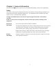
Specifications Model Number Input Output Max Signal Voltage Max Signal Current Battery type Same for All Models 12V 7.2AHr Spill-Proof, Maintenance-Free, Sealed Lead Acid CP15U48 100-240V 50-60Hz 1.0A 48V 15W 30V 5mA CP24U12 100-240V 50-60Hz 1.0A 12V 24W 30V 5mA CP40U48 100-240V 50-60Hz 1.
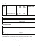
Chapter 2 Installation Enclosure Installation Install the UPS in a protected area that is free of excessive dust and has adequate airflow. Do not operate the power supply where the temperature and humidity are outside the specified limits. Refer to Specifications in this manual. Install the UPS inside a building in a protected area that is free of excessive dust and has adequate airflow. Use screws that are appropriate for the weight of this unit and the mounting surface material.
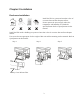
Battery Installation Step 2 Step 3 Step 1 Red Cable Black Cable Positive Terminal Battery Cover Release Tabs Negative Terminal Battery Replacement This UPS has an easy to replace, hot-swappable battery. Replacement is a safe procedure, isolated from electrical hazards. You may leave the UPS and connected equipment on for this procedure. Replace the spent battery with replacement battery RBC40. See your dealer or refer to the APC Web site, www.apc.com for information on replacement battery modules.
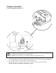
Chapter 3 Operation Connect Equipment and Power Utility Power Cord Inlet Communication Signals Cold Start The UPS battery charges when it is connected to utility power. The battery charges fully during the first eight hours of normal operation. Do not expect full battery run capability during this initial charge period. 1. Connect equipment to the UPS communication signals via the seven-pin connector (included), or use an APC custom data cable, (must be ordered separately). 2.
Status Indicators UPS Front View Status Indicators Green indicates the UPS is on utility power. Yellow indicates the UPS is on battery power. Green indicates DC output power is provided by the battery or utility power. Red indicates that the battery is not connected or the battery needs to be replaced. Refer to the Battery Replacement section. Communication Signals The PowerShield communication signals are isolated from its internal circuitry via open collector opto-coupled transistors.
7
Chapter 4 Service, Contact and Warranty Information Service APC makes every effort to ensure parts and equipment arrive in working condition. Occasionally, it may be necessary to return parts or equipment that are not in working condition. If the UPS requires service, follow these steps: 1. 2. Contact APC Customer Support through the APC Web site, www.apc.com. Note the product model number, the serial number, and the date purchased.
Limited Warranty American Power Conversion (APC) warrants its products to be free from defects in materials and workmanship for a period of two years from the date of purchase. Its obligation under this warranty is limited to repairing or replacing, at its own sole option, any such defective products. To obtain service under warranty you must obtain a Returned Material Authorization (RMA) number from customer support.
10