
Installation manual


85Uniflair LE Accessories Manual
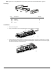
4. Insert the required jumpers. The following graphic provides jumper connection details.
• Jumpers P1, P2, and P3 are located inside the front opening of the cover.
• Jumper P1 adds a 510 ohm polarization resistance between the negative data line (-) and GND.
• Jumper P2 adds a 120 ohm terminal resistance between the two data lines (+) and (-).
• Jumper P3 adds a 510 ohm polarization resistance between the positive data line (+) and the +5 Vdc
internal voltage.
Insert all three jumpers on the unit at the start of the network and the unit at the end of the network. Do not
insert the jumpers on the intermediate units.
N
OTE: If the device used to read the data from the 485 network is grounded, and the RS232-RS485 converter
or the RS485 serial port on the device have functional insulation of less than 2kV, the connector G0 on the pCO
board must be grounded. The board cannot be installed in direct contact with the metal panel on the electrical
panel.
5. Connect the communication cable. Wind the cord around a ferrite core (field supplied.)
6. Replace the cover supplied with the pCOnet controller.
Configuration using the LED display
NOTE: If installing multiple units on the network, each unit requires a unique address to avoid conflicts.
1. Press Prg on the display interface.
2. Select SETTINGS.
3. Enter the password.
4. Select SERIAL/MODEM SETTINGS.
5. Enter the following:
Serial Address
Serial Speed
Protocol: STANDARD
6. Navigate to the main screen.
Configuration using the touchscreen
Path: Main > Configuration > Unit > Communication
1. Turn on the power to the unit and wait for the touchscreen to display.