Operation and Maintenance InRow® RC ACRC100 ACRC103
This manual is available in English on the enclosed CD. Dieses Handbuch ist in Deutsch auf der beiliegenden CD-ROM verfügbar. Deze handleiding staat in het Nederlands op de bijgevoegde cd. Este manual está disponible en español en el CD-ROM adjunto. Ce manuel est disponible en français sur le CD-ROM ci-inclus. Questo manuale è disponibile in italiano nel CD-ROM allegato. 本マニュアルの日本語版は同梱の CD-ROM からご覧になれます。 Instrukcja Obsługi w jezyku polskim jest dostepna na CD.
Important Information APC Legal Disclaimer The information presented in this manual is not warranted by the American Power Conversion Corporation to be authoritative, error free or complete.
Contents General Information ........................................................ 1 Overview . . . . . . . . . . . . . . . . . . . . . . . . . . . . . . . . . . . . . . . . . . . . . . . . 1 Save these instructions . . . . . . . . . . . . . . . . . . . . . . . . . . . . . . . . . . . 1 Intended users . . . . . . . . . . . . . . . . . . . . . . . . . . . . . . . . . . . . . . . . . . 1 Manual updates . . . . . . . . . . . . . . . . . . . . . . . . . . . . . . . . . . . . . . . . . .
Set Up Contacts . . . . . . . . . . . . . . . . . . . . . . . . . . . . . . . . . . . . . . . . . 12 Input and output contacts . . . . . . . . . . . . . . . . . . . . . . . . . . . . . . . . . 12 Set Up Cooling Group Configuration . . . . . . . . . . . . . . . . . . . . . . . . 13 Configure the cooling group . . . . . . . . . . . . . . . . . . . . . . . . . . . . . . 13 Identify the cooling unit . . . . . . . . . . . . . . . . . . . . . . . . . . . . . . . . . . 13 Configure Modbus . . . . . . . . . . . .
Quick Configuration . . . . . . . . . . . . . . . . . . . . . . . . . . . . . . . . . . . . . .27 Overview . . . . . . . . . . . . . . . . . . . . . . . . . . . . . . . . . . . . . . . . . . . . . . . 27 TCP/IP configuration methods . . . . . . . . . . . . . . . . . . . . . . . . . . . . . 27 APC Device IP Configuration Wizard . . . . . . . . . . . . . . . . . . . . . . . . 28 BOOTP & DHCP configuration . . . . . . . . . . . . . . . . . . . . . . . . . . . . . 28 Remote access to the control console . . . .
Warranty Procedures . . . . . . . . . . . . . . . . . . . . . . . . . . . . . . . . . . . . . 43 Claims . . . . . . . . . . . . . . . . . . . . . . . . . . . . . . . . . . . . . . . . . . . . . . . . . 43 Parts . . . . . . . . . . . . . . . . . . . . . . . . . . . . . . . . . . . . . . . . . . . . . . . . . .
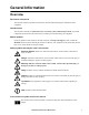
General Information Overview Save these instructions This manual contains important instructions that must be followed during the installation of this equipment. Intended users This manual is intended for American Power Conversion (APC) authorized personnel. It provides component specifications and instructions for installing and commissioning the equipment. Manual updates Check for updates to this manual on the APC Web site, www.apc.com/support.
Safety Note: All work should be performed by American Power Conversion (APC®) authorized personnel only. Caution: Keep your hands, clothing, and jewelry away from moving parts. Check the equipment for foreign objects before closing the doors and starting the equipment. Heavy: The equipment is heavy. For safety purposes, at least two people must be present when moving this equipment. Tip Hazard: This equipment has a high center-of-gravity. Use extreme caution when moving.
Operation Display Interface Sta tus ESC Check Log ? Wa rn in g na1582a Cr itical Item Function Critical Alarm LED When red, a critical alarm condition exists and requires your immediate attention. Warning Alarm LED When yellow, a warning alarm condition exists. Failure to correct this condition could cause a critical alarm. Check Log LED When yellow, at least one new critical alarm or warning alarm or event has occurred.
Using the Display Every time you apply power to the APC InRow RC, the display initializes and runs an LED and alarmtone test. Scrolling status screens After start-up, the interface displays the firmware revision number of the display interface.The display interface then scrolls automatically and continuously through screens of status information. Press the up or down arrow key to interrupt the automatic scrolling and view a specific status screen. Press ESC to switch to the main menu.
Navigating the main menu Clear Event Log Configure Modbus Set Date & Time Set Password na1623d Selector arrow. Press the up or down arrow key to move the selector arrow to a main menu option. Press the ENTER key to view the selected sub-menu screen. In the example shown below, the selector arrow points to the Set Date and Time setting. Note: If the selector arrow is on the top line of a main menu screen, press the up arrow key to move the selector arrow to the top line of the previous screen.
Using the Path statement Select the main- and sub-menu options specified in the path statement to view or configure a setting. The path statement lists the main- and sub-menu options you select to navigate to the setting you want to view or modify. The parts of the path statement are defined in the following example: Path: Main Menu>Set Password>Change Passwords Main Menu> Your starting point is the main menu. Set Password> Scroll to and select this option from the main menu.
Start the cooling unit Path: Main Menu>On/Standby>Operate Press the ENTER key to change the setting to On. The cooling unit will run according to the configured settings. Stop the cooling unit Path: Main Menu>On/Standby>Operate: Press the ENTER key to change the setting to Standby. The cooling unit will enter the standby mode. Warning: The Standby option does not remove power from the cooling unit. You must disconnect all power sources to remove power from the cooling unit.
Commissioning Warning: Procedures in this chapter should only be performed by qualified, APC-trained personnel. Warning: Equipment must be properly de-energized and locked-out before performing any service. After installation, complete the following checklists to verify that all components are working properly and that the equipment is ready to begin operation. Checklists Initial inspection Ensure that the: Installation procedure is complete according to the installation manual.
Mechanical inspection Ensure that the: Condensate drain line is the size of the drain connection and is routed properly. Mechanical connections are tight. Equipment has isolation valves installed for removal of the equipment from a row for servicing. Piping is insulated. Equipment has strainers installed into the supply piping. Piping does not have any leaks. External chilled water isolation valves are open. Air is bled from the system.
Start-up Caution: Starting the equipment in a high-humidity environment may lead to excessive condensation and equipment shutdown. Start-up sequence 1. Close all doors and windows. Ensure the room is sealed. See “Room Preparation” in the InRow RC Installation manual. 2. Run the room cooling equipment until the “Acceptable Operating Conditions” dry bulb temperature (db ºC or db ºF) and relative humidity (% RH) zone indicated in the chart below are reached.
Set Up General Configuration The cooling group configuration options are set during the commissioning of the cooling units in the cooling group. Caution: Changing the settings incorrectly can cause malfunctions to your cooling unit. Only qualified service personnel should make changes to these settings. Cooling unit configuration Path: Main > Configure Unit > General Capacity.
Set Up Contacts Input and output contacts Path: Main > Configure Unit > Discrete I/O Each cooling unit supports a user-defined input contact and a user-defined output contact. Each contact monitors a sensor and responds to changes in the state of the sensor (open or closed). Input State. Indicates the actual state of the input contact (open or closed). A cooling unit is On when the state is normal and in Standby mode when the state is not normal. Output State.
Set Up Cooling Group Configuration The cooling group configuration determines how the cooling group should operate. Caution: The settings in the Cooling Group Configuration menu are defined by the field service representative when the cooling group is commissioned. Only qualified service personnel should make changes to these settings.
Control the Environment The InRow RC utilizes a chilled water coil, a valve to modulate fluid flow through the chilled water coil, and a set of fans to control airflow through the coil. The control strategies employed by the cooling unit depend upon the deployment strategy of the cooling group. In an In-Row environment, the InRow RC supplies constant-temperature supply air to the common cold aisle. The fan speed is modulated to ensure that the required volume of air reaches the IT equipment.
PID settings Path: Main > Set Group PID The Proportional plus Integral plus Derivative (PID) loop is used to control the output of the cooling group. The PID settings apply only when using the In-Row rack deployment strategy. See “Configure the cooling group” on page 13 for information on selecting a rack deployment strategy. Gain (P). The proportional multiplier (gain) for this mode or actuator.
Tune the PID loop A qualified service technician must tune the PID loop to optimize the performance of the cooling group. Caution: The PID loop must be tuned after the equipment in the room is installed and running. The loop should be tuned periodically to account for changes in the room load. 1. Adjust the integral and derivative constants to zero and the proportional constant to 0.7. 2. Set the temperature setpoint value and start the cooling group. 3.
Run hours The cooling unit records the number of hours each of its components has operated. When a component is replaced, use the Reset option to reset the run hours for the displayed component to zero.
Set Up the Display Set display settings including the time and date, temperature units, passwords, and time-out settings. Password and time-out Path: Main > Set Password Note: The default user password is apc (lower case). See “Password entry” on page 6 for more information on how to enter the password. Change passwords. 1. Move the selector arrow next to the Change Passwords option and press the ENTER key. 2.
View Status Readings The display interface provides several options for viewing the status of the cooling group, its cooling units, and the environment being controlled. The status readings for cooling units are available under the View Unit Status menu, and status readings for the cooling group are available under the View Group Status menu or on the scrolling status screens. Scrolling status screens When the display interface is idle, it scrolls through screens of status information.
Cooling group status Path: Main > View Group Status The cooling group status screens provide information about the cooling group. Cool Output. The actual cooling output of the cooling group. Cool Demand. The output required to meet the current heat load of the conditioned space. Cool Setpoint. The temperature you set that the air entering the rack should maintain. Max Rack. The highest rack temperature reported by any cooling unit in the cooling group. Min Rack.
Event Log The event log saves status information and a message each time a change in the Group is detected. Alarms and events are recorded in the log and displayed on the active alarm screens; however, status (informational) events are displayed only in the event log. View event log Path: Main > View Event Log The event log keeps a record of all alarms and events.
Alarm messages and suggested actions Note: Critical alarm—An alarm that requires immediate action and prevents the system from performing at its rated cooling capacity. Warning alarm—An alarm that requires attention and could jeopardize your data or equipment if its cause is not addressed. Displayed Alarm Message Severity Action Required Air Containment High Pressure Fault Warning • Make sure the sensor is connected properly.
Displayed Alarm Message Severity Action Required Entering Fluid Temperature Sensor Fault Warning • Make sure the sensor is connected properly. • Replace the sensor. • For assistance, contact APC Customer Support. See the back cover of this manual for contact information. Supply Temperature Sensor na1989a Return Temperature Sensor Fan #n Fault Warning • Make sure all air intakes are clear of any blockage. Note: Fans are numbered sequentially, starting with Fan 1 at the bottom.
Displayed Alarm Message Severity Action Required Group Communication Lost Warning • Make sure the number of units in the group is configured properly and the A-Link connections between units are correct. Also, make sure the group is receiving power and all connections are properly made. • For assistance, contact APC Customer Support. See the back cover of this manual for contact information. Internal Communications Fault Critical • For assistance, contact APC Customer Support.
Displayed Alarm Message Severity Action Required Return High Temperature Violation Warning • Make sure the temperature sensor is connected properly. • Make sure the Return Air threshold is set correctly in the High Temp Threshlds screen. • If the problem persists, replace the sensor. • For assistance, contact APC Customer Support. See the back cover of this manual for contact information. Supply Air High Temperature Violation Warning • Make sure the temperature sensor is connected properly.
Network Management Card Set Up Network Configuration Configure the network settings for the Network Management Card from the display interface. The management card allows remote control and configuration of the InRow RC. Network configuration Path: Main > Configure Network MAC Address. Displays the unique network identifier assigned to the Network Management Card at the factory. Path: Main > Configure Network > IP Address You will be prompted to enter an Admin password.
Quick Configuration The InRow RC is shipped with a Network Management Card that allows for the management of the air conditioner over your network. You must set up the Network Management Card in order to control the InRow RC through its Web interface or through the control console. Overview You must configure the following TCP/IP settings before the InRow RC can operate on a network: • IP address of the Network Management Card • Subnet mask • Default gateway Note: Never use the loopback address (127.0.0.
APC Device IP Configuration Wizard You can use the APC Device IP Configuration Wizard at a computer running Microsoft® Windows® 2000, Windows 2003, or Windows XP to configure a Network Management Card. To configure one or more Network Management Cards from a user configuration file, see the User’s Guide on the Utility CD. 1. Insert the Utility CD into a computer on your network. 2. Select Device IP Configuration Wizard from the main menu. 3.
DHCP. You can use a RFC2131/RFC2132-compliant DHCP server to configure the TCP/IP settings for the Network Management Card. This section summarizes communication between the Network Management Card and a DHCP server. For more detail about how a DHCP can configure the network settings for a Network Management Card, see “DHCP Configuration” in the APC InRow RC User’s Guide on the Utility CD. 1.
Remote access to the control console From any computer on the same network as the Network Management Card, you can use ARP and Ping to assign an IP address to the Network Management Card and then use Telnet to access the control console of that Network Management Card and configure the other TCP/IP settings. Note: After a Network Management Card has its IP address configured, you can use Telnet, without first using ARP and Ping, to access that Network Management Card. 1.
Control console After you log on at the control console, as described in “Remote access to the control console” on page 30: 1. Choose Network from the Control Console menu. 2. Choose TCP/IP from the Network menu. 3. If you are not using a BOOTP or DHCP server to configure the TCP/IP settings, select the Boot Mode menu. Select Manual boot mode, and then press ESC to return to the TCP/IP menu. (Changes will take effect when you log out.) 4. Set the System IP, Subnet Mask, and Default Gateway address values.
Telnet/SSH You can access the control console through Telnet or Secure SHell (SSH), depending on which is enabled. (To enable these access methods, select the Administration tab, then Network on the top menu bar, and the access option under Console on the left navigation menu.) By default, Telnet is enabled. Enabling SSH automatically disables Telnet. Telnet for basic access. Telnet provides the basic security of authentication by user name and password, but not the high-security benefits of encryption.
Simple Network Management Protocol (SNMP) SNMPv1 only. After you add the PowerNet® MIB to a standard SNMP MIB browser, you can use that browser to access the InRow RC. All user names, passwords, and community names for SNMP are transferred over the network as plain text. The default read community name is public; the default read/ write community name is private. SNMPv3 only. For SNMP GETs, SETs, and trap receivers, SNMPv3 uses a system of user profiles to identify users.
Recovering From a Lost Password Use a local computer (a computer that connects to the InRow RC through the serial port) to access the control console. Note: To access the serial port, remove the rear panel and lower air filter of the InRow RC. na2005a 1. Select a serial port at the local computer, and disable any service that uses that port. 2.
Maintenance Monthly Preventive Maintenance The following pages can be photocopied and used during the maintenance procedures. After they have been filled out, save them for future reference.
Mechanical Check the fans. All components should be moving freely with no signs of binding or damages. Verify that the condensate line is flowing freely. Verify the chilled water supply temperature for cooling unit. Chilled water supply temperature________________________ Electrical Before checking the electrical connections shut off and lock out the power to the cooling unit. Inspect the electrical panel for tight connections and overheated connections from loose contact terminals.
Semi-Annual Preventive Maintenance Perform all the Monthly/Quarterly Preventive Maintenance items and the items below. Prepared By: _________________________________ Model Number: ______________________________ Serial Number: _______________________________ Date: _________________ Cleanliness Cleaning the evaporator coil requires unlocking and removing the side panels. Before you remove the side panels, you must shut off and lock out the power to the cooling unit.
Troubleshooting Problem Possible Cause Corrective Action Controls are erratic or inoperative • Inlet temperature to cooling unit is higher than rated maximum temperature • Reduce the load or add additional cooling equipment. • Cooling unit is not properly tuned • Tune the PID settings. • Power supplies are not operating properly • Confirm that the power supplies are seated properly and fully engaged. This is indicated by a green LED.
Problem Possible Cause Corrective Action Water carryover • Improper fan speed selected • Select the next highest fan speed setting. For example, change the fan speed setting from Low to Med/Low. • Inlet water temperature is too low • Verify that the temperature of the inlet water is within the specified range. • Room humidity is too high • Adjust setpoint on dehumidifying equipment. • Add additional dehumidifying equipment. • Dirty coil • Clean the coil. • Dirty filter • Clean the air filter.
Problem Possible Cause Corrective Action Alarms do not show up on monitoring equipment (Form C) • External monitoring equipment is not receiving power or is not functioning properly • Confirm that power, if required, is being supplied to the external equipment. • If the cooling unit is providing power (+12 V or +24 V) to the external equipment, verify that the external equipment is <50 mA. • Test the external equipment by bypassing the Form C.
Warranty One-Year Factory Warranty The limited warranty provided by American Power Conversion (APC®) in this Statement of Limited Factory Warranty applies only to products you purchase for your commercial or industrial use in the ordinary course of your business. Terms of warranty American Power Conversion warrants its products to be free from defects in materials and workmanship for a period of one year from the date of purchase.
IN NO EVENT SHALL APC, ITS OFFICERS, DIRECTORS, AFFILIATES OR EMPLOYEES BE LIABLE FOR ANY FORM OF INDIRECT, SPECIAL, CONSEQUENTIAL OR PUNITIVE DAMAGES, ARISING OUT OF THE USE, SERVICE OR INSTALLATION, OF THE PRODUCTS, WHETHER SUCH DAMAGES ARISE IN CONTRACT OR TORT, IRRESPECTIVE OF FAULT, NEGLIGENCE OR STRICT LIABILITY OR WHETHER APC HAS BEEN ADVISED IN ADVANCE OF THE POSSIBILITY OF SUCH DAMAGES.
Warranty Procedures Claims To obtain service under the warranty, contact APC Customer Support (see the back cover of this manual for contact information). You will need the model number of the Product, the serial number, and the date purchased. A technician will also ask you to describe the problem. If it is determined that the Product will need to be returned to APC, you must obtain a returned material authorization (RMA) number from APC Customer Support.
Index A Adjust the screen 18 Admin password 6 Air filter interval 17 Arrow keys 3 B Beeper disable key click 18 Boot mode 26 C Check log LED 3 Clear alarms option 21 Clear event log option 21 Contacts input contacts 12 Continue arrow 5 Contrast adjust LCD 18 Control console 31 remote access 30 Control environment PID settings 15 Cooling Group status 20 Cooling unit identification 13 Cooling unit options configuration 11 idle on leak 11 start-up delay 11 Cooling unit status 19 Critical Alarm LED 3 D D (PI
Password admin 6 changing 18 device 6 invalidate 18 time-out 18 PID controls D (derivative) 15 gain setting 15 I (integral) 15 P (proportional) 15 reset rate 15 tuning 16 PID settings 15 Proportional 15 Thresholds high temperature 17 Time set the time 18 Time-out password 18 Tuning PIDs 16 V View alarms option 21 W Warning Alarm LED 3 Web interface 31 R Reset Rate 15 Respond to alarms clear alarms 21 view alarms 21 Return air 17 Run hours 17 S Screen icons continue arrow 5 input arrow 5 selector arrow
Radio Frequency Interference Changes or modifications to this unit not expressly approved by the party responsible for compliance could void the user’s authority to operate this equipment. USA—FCC This equipment has been tested and found to comply with the limits for a Class A digital device, pursuant to part 15 of the FCC Rules. These limits are designed to provide reasonable protection against harmful interference when the equipment is operated in a commercial environment.
APC Worldwide Customer Support Customer support for this or any other APC product is available at no charge in any of the following ways: • Visit the APC Web site to access documents in the APC Knowledge Base and to submit customer support requests. – www.apc.com (Corporate Headquarters) Connect to localized APC Web sites for specific countries, each of which provides customer support information. – www.apc.com/support/ Global support searching APC Knowledge Base and using e-support.