Installation InRow™ Half-Rack RC ACRC100 ACRC103
This manual is available in English on the enclosed CD. Dieses Handbuch ist in Deutsch auf der beiliegenden CD-ROM verfügbar. Deze handleiding staat in het Nederlands op de bijgevoegde cd. Este manual está disponible en español en el CD-ROM adjunto. Ce manuel est disponible en français sur le CD-ROM ci-inclus. Questo manuale è disponibile in italiano nel CD-ROM allegato. 本マニュアルの日本語版は同梱の CD-ROM からご覧になれます。 Instrukcja Obsługi w jezyku polskim jest dostepna na CD.
American Power Conversion Legal Disclaimer The information presented in this manual is not warranted by the American Power Conversion Corporation to be authoritative, error free, or complete. This publication is not meant to be a substitute for a detailed operational and site specific development plan.
Contents General Information ........................................................ 1 Overview . . . . . . . . . . . . . . . . . . . . . . . . . . . . . . . . . . . . . . . . . . . . . . . . 1 Save these instructions . . . . . . . . . . . . . . . . . . . . . . . . . . . . . . . . . . . 1 Intended users . . . . . . . . . . . . . . . . . . . . . . . . . . . . . . . . . . . . . . . . . . 1 Manual updates . . . . . . . . . . . . . . . . . . . . . . . . . . . . . . . . . . . . . . . . . .
Stabilizing the Equipment . . . . . . . . . . . . . . . . . . . . . . . . . . . . . . . . . 15 Floor brackets . . . . . . . . . . . . . . . . . . . . . . . . . . . . . . . . . . . . . . . . . . 15 Joining to enclosures . . . . . . . . . . . . . . . . . . . . . . . . . . . . . . . . . . . . 15 Mechanical Connections . . . . . . . . . . . . . . . . . . . . . . . . . . . . . . . . . . 16 Piping . . . . . . . . . . . . . . . . . . . . . . . . . . . . . . . . . . . . . . . . . . . . . . . . .
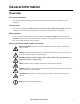
General Information Overview Save these instructions This manual contains important instructions that must be followed during the installation of this equipment. Intended users This manual is intended for American Power Conversion (APC) authorized personnel. It provides component specifications and instructions for installing and commissioning the equipment. Manual updates Check for updates to this manual on the APC Web site, www.apc.com/support.
Cross-reference symbol used in this manual See another section of this document or another document for more information on this subject. Safety Electrical Hazard: This equipment has multiple power sources. Disconnect all power sources before servicing the equipment. Do not wear jewelry when working near energized components. Heavy: This equipment is heavy. For safety, at least two people must be present when moving or installing it. Tip Hazard: This equipment has a high center-of-gravity.
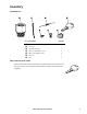
Inventory na2329a Installation kit Item Description Quantity 1-in NPT to 1-in BSPT adapters 2 Tie wraps 3 Termination resistor 1 M5 x 12 mm Phillips screws 4 M4 x 8 mm Phillips screws 4 Wire clip 3 Key 2 Door and side panel locks The four side panels are locked at the factory, and the front and rear doors are not locked. Two keys are in the plastic documentation envelope located inside the equipment.
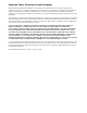
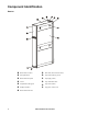
Component Identification na1542a Exterior 4 Removable rear door Door lock (front and rear doors) Side panel latch Top network wiring access Removable side panel Top supply (inlet) Caster Top condensate drain Adjustable leveling foot Top return (outlet) Display interface Top power cord access Removable front door InRow Half-Rack RC Installation
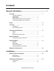
na1556a Interior Air filter Bottom supply connection (optional) Top supply connection (optional) User interface connection box Top return connection (optional) Condensate pump 2-way supply valve (1-inch) Power supply unit (PSU) Flow meter Bottom condensate drain pan 3-way valve Condensate floats 2-way or 3-way valve with flow control actuator Coil 2-way valve (3/4-inch) bypass shut-off Top condensate drain pan Bottom return connection (opt
na2236a User interface connection panel 6 A-Link ports Control RS-485 port Reset button Form C alarm contacts and shutdown input Ethernet port Configuration port Building management system (BMS) RS-485 port Leak detector port InRow Half-Rack RC Installation
Room Preparation During the design of the data center, consider ease of entry for the equipment, floor loading factors, and accessibility to piping and wiring. Seal the room with a vapor barrier to minimize moisture infiltration. (Polyethylene film is recommended for ceiling and wall applications.) Apply rubber- or plastic-based paints to concrete walls and floors. Insulate the room to minimize the influence of exterior heat loads.
Piping Diagrams With CDU To customersupplied chiller Top piping InRow RC CDU Supports up to 12 units Bottom piping CDU InRow RC Supports up to 12 units na2608a To customersupplied chiller Flex hose or copper tubing Y-strainer with 20 mesh screen (field installed) Copper tubing Shutoff valve (field-installed) Note: Install isolation valves and particulate strainers with 20 mesh stainless steel screen (opening size = 865 micron) in the supply line between the chiller and the CDU.
Without CDU Top piping To customersupplied chiller InRow RC InRow RC Bottom piping InRow RC InRow RC na2609a To customersupplied chiller Flex hose or copper Copper tubing Y-strainer with 20 mesh screen (field installed) Shutoff valve (field-installed) Circuit setter Note: Install isolation valves and particulate strainers with 20 mesh stainless steel screen (opening size = 865 micron) in the supply line between the chiller and the CDU.
na1736b Internal piping diagram 10 Entering water union (top piping) Entering water union (bottom piping) Leaving water union (top piping) Bottom condensate pan 3-way actuator control valve—3/4 in Bottom coil Bypass shutoff ball valve—3/4 in Top condensate pan Condensate drain Top coil Leaving water union (bottom piping) Flow meter Condensate pump Inlet shutoff valve—1 in InRow Half-Rack RC Installation
117 (4.6) 80 (3.15) 152.00 (5.98) 67.80 (2.67) 48.00 (1.89) 0 222 (8.74) 149 (5.87 ) 73 (2.87) 50 (1.97) 0 Piping and electrical access locations 0 114 (4.59) 152 (5.98) 190.55 (7.50) 229 (9.02) 507.50 (19.98) Bottom na1557a Top Supply 173 (6.80) 414 ( 16.28) Return Interior pipe dimensions Supply 629 ( 24.78) 445 (17.51) Return Dimensions are shown in mm (in).
na1551a Weights and Dimensions Dimensions are shown in mm (in). Net weight (equipment only) 12 162.77 kg (358.
Installation Removing Doors and Panels Door removal Warning: Do not open doors and panels if the equipment is operating. na1571a Caution: Spring latches can be damaged if the doors are placed against an object with the latches contacting the object.
Positioning the Equipment Service access na1565a An area of 1143 mm (45 in) of clear floor space in front and 914.4 mm (36 in) in back of the equipment is required for service. All required maintenance can be performed from the front or back of the equipment. Dimensions are shown in mm (in). Leveling The leveling feet provide a stable base if the floor is uneven, but cannot compensate for a badly sloped surface.
Stabilizing the Equipment Floor brackets To prevent the equipment from moving from its final location (if it is not joined with an enclosure), use the included bolt-down kit (AR7701). Follow the installation instructions included with the kit. Joining to enclosures NetShelter® SX enclosure. Two joining brackets are installed on the front and rear of the equipment. Depending on how the holes on the joining brackets are used, you have the option of either 24-in or 600-mm spacing. 2.
Mechanical Connections Piping Hot Aisle Containment Water. Install shutoff valves for routine service and emergency isolation of the equipment. When a cooling distribution unit (CDU) is not used, you must install circuit setters to regulate the chilled water flow for each InRow RC air conditioner. See piping diagrams beginning on page 8. CDU NetShelter NetShelter NetShelter Top piping examples shown UPS PDU Layout and piping NetShelter RC considerations.
Connect piping See “Piping Diagrams,” beginning on page 8, for recommended valve, flexible adapter, and strainer installation locations. 1. Route all piping to the InRow RC in compliance with all local and national codes. Note: Circuit setters are required to regulate the flow of chilled water to each piece of equipment. When a CDU is used in conjunction with the equipment, circuit setters are not required, as the CDU provides the flow-regulating function.
Condensate pump drain connection. Condensate drain line Note: Sufficient PVC drain line is supplied to route the drain to the outside of the equipment. To route the drain line to a remote drain, obtain additional hardware. Condensate pump drain installation. The condensate drain line is coiled inside the equipment, allowing you to route the condensate drain line for either top or bottom use. See the table “Piping and electrical access locations” on page 11 for more information.
CDU See the CDU Installation manual for proper installation procedures. Accessories and spare parts Accessories are available for the equipment, including flexible pipe adapters, data troughs, data partitions, and height adapters for use with other APC equipment. For more information, contact APC at a number on the back cover of this manual. Many serviceable components are available as spare parts. For more information, contact APC at a number on the back cover of this manual.
Filling and Purging When the equipment is properly piped, begin the filling process (top piping configuration shown). Electrical Hazard: Ensure both electrical connections are disconnected before introducing water into the equipment. 1. Open the 2-way supply valve and the 2-way bypass shutoff valve. 2. Using a 2.5-mm hex key, turn the flow control actuator to the fully open position.
3. Slightly open the top coil vent. 4. At the water supply, open the appropriate valves to begin letting water slowly enter the equipment. 5. At the equipment, close the top coil vent when water begins slowly flowing out of the vent. Top coil vent a. Open all valves (no greater than 76 l/m [20 gpm]), allowing the water supply to reach the highest possible flow to the equipment for 45 seconds. na1768a 6. At the water supply: b. Close the valves to a 3.8–11.4 l/m (1–3 GPM) flow for 60 seconds. c.
Electrical Connections The following electrical connections are required in the field: • Feeds A and B • A-Link • Network Management Card • Temperature sensor • Communication (building management system) See the electrical schematic, located on the lid of the electrical box, for all electrical connections. All electrical connections must be in accordance with national and local codes. See the InRow RC nameplate for voltage and current requirements.
Power connections Warning: The equipment has two power inputs for redundancy. Disconnect both before performing any service. Power cords may be routed through the top of the equipment (standard) or through the bottom (optional). Top wiring configuration Screws Top power cord entrance (standard). 1. Route power cords through the equipment to the top power cord access, as shown. 2. Push the power cords through the hole at the top power cord entrance. 3.
Feeds A and B. The equipment is capable of receiving power through one of two separate feeds, feed A or feed B. Use the display interface to configure the unit to receive power through feed A, feed B, or both). If connected, feed B is the primary power input to the equipment by default; feed A is the backup power input. The equipment receives power through feed B regardless of whether feed A is receiving power.
User interface connection pinout Shutdown input contacts and alarm output contacts CONTROL na1579a MODBUS A-Link port Pin 1=High; Pin 2=Low; Pins 3, 6=Perf Power; Pins 4, 5=Ground 24 Vdc (bias) Reset button 12 Vdc (bias) Network port Return (bias) Pins 1-8 = Standard RJ-45 Shield/ground NO (normally open contact) A-=True COM (common contact) B+=True NC (normally closed contact) Shutdown - RS-232 console port (see the InRow RC Service Manual) Sh
A-Link ports Note: All input and output connections should be wired as Class 2 circuits. Depending on the equipment configuration, additional control connections may be required for the A-Link remote communications through APC Network Management Card support or other equipmentmonitoring software. A special RJ-45 terminator is provided and must be installed if both A-Link ports are not otherwise used, as shown.
Network port Second InRow RC Switch/Hub Last InRow RC na2247a First InRow RC LAN cable (10/100 Base-T) InRow Half-Rack RC Installation 27
Modbus First InRow RC Second InRow RC Last InRow RC na2248a Modbus MASTER 28 150Ω termination resistor (provided) Modbus cable (RS-485) InRow Half-Rack RC Installation
na2249a Control connector 150Ω termination resistor (provided) Control cable (RS-485) Peripheral device (example: chiller) na2250a Form C alarm contacts and shutdown input A relay internal to the user interface is typically controlled by a user-defined alarm (malfunctioning fans, for example). Before an alarm is detected, the voltage on the COM terminal is routed to the NC terminal.
Leak detector port na1584a Rope water detector (AP9325). Up to four optional rope water detectors can be installed in series. The rope water detector connects to the RJ-45 leak detector port located at the top of the interface box. See the “Rope Water Detector” installation sheet, supplied with the kit, for installation and setup information.
Install the temperature sensor. 1. Insert the rack temperature sensor connector in the temperature sensor port at the user interface. See “User interface connection pinout” on page 25. a. For a top installation, push the rack temperature sensor through the wire channel located at the top of the equipment in the left hand side just above the user interface connectors. Temperature sensor Wire clip 2. Route the sensor through either the top or the bottom of the adjacent server rack. 3.
Specifications Electrical Input voltage 100-240 V; 50/60 Hz; 1 Ph Rated current 10.1 A at 100 V 9.2 A at 120 V 5.1 A at 208 V 4.6 A at 230 V 4.4 A at 240 V Condensate pump 5 l/h (1.3 GPH), 4.9-m (16-ft) vertical rise, 15-m (50-ft) horizontal run Physical Physical dimensions W xDxH 300 x 1068.9 x 1991.1 mm (11.80 x 42.08 x 78.39 in) Net weight (InRow RC only) 162.77 kg (358.5 lb) Shipping weight 192.77 kg (425.0 lb) 355.62 kg (784.0 lb) Single Double Environmental Cooling capacity 18.
Warranty One-Year Factory Warranty The limited warranty provided by American Power Conversion (APC®) in this Statement of Limited Factory Warranty applies only to products you purchase for your commercial or industrial use in the ordinary course of your business. Terms of warranty American Power Conversion warrants its products to be free from defects in materials and workmanship for a period of one year from the date of purchase.
IN NO EVENT SHALL APC, ITS OFFICERS, DIRECTORS, AFFILIATES OR EMPLOYEES BE LIABLE FOR ANY FORM OF INDIRECT, SPECIAL, CONSEQUENTIAL OR PUNITIVE DAMAGES, ARISING OUT OF THE USE, SERVICE OR INSTALLATION, OF THE PRODUCTS, WHETHER SUCH DAMAGES ARISE IN CONTRACT OR TORT, IRRESPECTIVE OF FAULT, NEGLIGENCE OR STRICT LIABILITY OR WHETHER APC HAS BEEN ADVISED IN ADVANCE OF THE POSSIBILITY OF SUCH DAMAGES.
Warranty Procedures Claims To obtain service under the warranty, contact APC Customer Support (see the back cover of this manual for contact information). You will need the model number of the Product, the serial number, and the date purchased. A technician will also ask you to describe the problem. If it is determined that the Product will need to be returned to APC, you must obtain a returned material authorization (RMA) number from APC Customer Support.
APC Worldwide Customer Support Customer support for this or any other APC product is available at no charge in any of the following ways: • Visit the APC Web site to access documents in the APC Knowledge Base and to submit customer support requests. – www.apc.com (Corporate Headquarters) Connect to localized APC Web sites for specific countries, each of which provides customer support information. – www.apc.com/support/ Global support searching APC Knowledge Base and using e-support.