Operation and Maintenance InfraStruXure® InRow RC ACRC100 ACRC101 ACRC103
This manual is available in English on the enclosed CD. Dieses Handbuch ist in Deutsch auf der beiliegenden CD-ROM verfügbar. Deze handleiding staat in het Nederlands op de bijgevoegde cd. Este manual está disponible en español en el CD-ROM adjunto. Ce manuel est disponible en français sur le CD-ROM ci-inclus. Questo manuale è disponibile in italiano nel CD-ROM allegato. 本マニュアルの日本語版は同梱の CD-ROM からご覧になれます。 Instrukcja Obsługi w jezyku polskim jest dostepna na CD.
Contents Operation.......................................................................... 1 Display Interface . . . . . . . . . . . . . . . . . . . . . . . . . . . . . . . . . . . . . . . . . .1 Using the Display . . . . . . . . . . . . . . . . . . . . . . . . . . . . . . . . . . . . . . . . .2 Scrolling status screens . . . . . . . . . . . . . . . . . . . . . . . . . . . . . . . . . . . 2 Main menu screens . . . . . . . . . . . . . . . . . . . . . . . . . . . . . . . . . . . . . . .
Set Up Network Configuration. . . . . . . . . . . . . . . . . . . . . . . . . . . . . . 17 Network configuration . . . . . . . . . . . . . . . . . . . . . . . . . . . . . . . . . . . 17 View Status Readings . . . . . . . . . . . . . . . . . . . . . . . . . . . . . . . . . . . . 18 Scrolling status screens . . . . . . . . . . . . . . . . . . . . . . . . . . . . . . . . . . 18 Cooling unit status . . . . . . . . . . . . . . . . . . . . . . . . . . . . . . . . . . . . . . 18 Cooling group status . . . . . . .
Maintenance ................................................................... 39 Monthly Preventive Maintenance. . . . . . . . . . . . . . . . . . . . . . . . . . . .39 Environment . . . . . . . . . . . . . . . . . . . . . . . . . . . . . . . . . . . . . . . . . . . . 39 Cleanliness . . . . . . . . . . . . . . . . . . . . . . . . . . . . . . . . . . . . . . . . . . . . . 39 Mechanical . . . . . . . . . . . . . . . . . . . . . . . . . . . . . . . . . . . . . . . . . . . . . 40 Electrical . . . . . . . . .
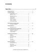
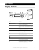
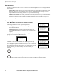
Operation Display Interface St atus ESC Check Log ? War ni ng na1582a Cri tical Item Function Critical Alarm LED When red, a critical alarm condition exists and requires your immediate attention. Warning Alarm LED When yellow, a warning alarm condition exists. Failure to correct this condition could cause a critical alarm. Check Log LED When yellow, at least one new critical alarm or warning alarm or event has occurred.
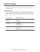
Using the Display Every time you apply power to the APC® InfraStruXure® InRow RC, the display initializes and runs an LED and alarm-tone test. Scrolling status screens After start-up, the interface displays the firmware revision number of the display interface.The display interface then scrolls automatically and continuously through screens of status information. Press the up or down arrow key to interrupt the automatic scrolling and view a specific status screen. Press ESC to switch to the main menu.
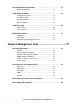
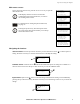
Operation: Using the Display On any top-level status screen, press the ENTER or ESC key to open the main menu screen. Note Note If the display interface is inactive for the time configured for the password time-out, it returns to the scrolling status screens. On/Standby View Alarms Clear Alarms View Event Log na1650a Main menu screens Clear Event Log Configure Modbus Set Date & Time Set Password For information on setting the password time-out, see page 15.
Operation: Using the Display Change settings Use the up or down arrow key to move the selector arrow to the setting that you wish to change, and press the ENTER key. • List of choices. If the setting is a list of choices, an input arrow is displayed next to the setting. Press the up or down arrow key to select the choice you want, and then press the ENTER key to exit the input mode and save the setting. Press the ESC key to exit without saving. • Numbers or text fields.
Operation: Using the Display Start the cooling unit Path: Main Menu > On/Standby To start the cooling unit, select the On/Standby option on the main menu and change the setting to On. The cooling unit will run according to the configured settings. Note On/Standby only affects the local cooling unit. You must set the On/Standby option for each cooling unit in the cooling group.
Set Up General Configuration The cooling group configuration options are set during the commissioning of the cooling units in the cooling group. Changing the settings incorrectly can cause malfunctions to your cooling unit. Only qualified service personnel should make changes to these settings. Caution Cooling unit configuration Path: Main > Configure Unit > General Use the General menu to set the following: Capacity.
Set Up Contacts Input/output contacts Path: Main > Configure Unit > Discrete I/O Input State: Open Output State: Open Normal State na1651a Each cooling unit supports a user-defined input contact and a user-defined output contact. Each contact monitors a sensor and responds to changes in the state of the sensor (open or closed). Input State. Indicates the actual state of the input contact (open or closed). A cooling unit is On when the state is normal, and in Standby when the state is not normal.
Set Up Cooling Group Configuration The cooling group configuration settings help the controller determine which components are available and how the cooling group should operate. Caution The settings in the Cooling Group Configuration menu are defined by the field service representative when the cooling group is commissioned. Only qualified service personnel should make changes to these settings.
Operation: Set Up Cooling Group Configuration Identify the cooling unit Path: Main > Set Identification The Set Identification menu contains settings that identify the name and location of the cooling units installed in this cooling group. Unit Id. Assign an identification number, from 1 through 12, to this cooling unit. User Defined Name. Assign a name of up to 19 alpha-numeric characters to this cooling unit. User Defined Loc. Enter the location, up to 19 alpha-numeric characters, of the cooling unit.
Control the Environment The InRow RC utilizes a chilled water coil, a valve to modulate fluid flow through the chilled water coil, and a set of fans to control airflow through the coil. The control strategies employed depend upon the deployment strategy of the cooling group. In an In-Row environment, the InRow RC supplies constant-temperature supply air to the common cold aisle. The fan speed is modulated to ensure that the desired volume of air reaches the IT equipment.
Operation: Control the Environment Fan Spd. Set the fan speed preference for the cooling group. Each fan speed provides an approximate temperature difference (DT) between the supply air from the InRow RC and the air returned from the rack. The cooling group will automatically override this fan speed setting and adjust the fan speed to provide optimum cooling for the rack as needed. Note • Low=30°F (16.7°C) DT • Med-Low=25°F (13.9°C) DT • Med=20°F (11.1°C) DT • Med-High=15°F (6.3°C) DT • High=10°F (5.
Operation: Control the Environment How to tune the PIDs A qualified service technician must tune the PID loop to optimize the performance of the cooling group. The PID loop must be tuned after the equipment in the room is installed and running. The loop should be tuned periodically to account for changes in the room load. Caution 1. Adjust the integral and derivative constants to zero, and the proportional constant to 0.7. 2. Set the temperature setpoint value and start the cooling group. 3.
Operation: Control the Environment Run hours The cooling unit records the number of hours each of its components has operated. When a component is replaced, use the Reset option to reset the run hours for the displayed component to zero.
Operation: Control the Environment Set alarms to alert you to high temperature violations and when components require service. Path: Main > Set Unit Thresholds On/Standby View Alarms Clear Alarms View Event Log When the air temperature exceeds the temperature defined by the High Temperature Threshold, an alarm will occur.
Set Up the Display Set display settings including the time and date, temperature units, passwords, and time-out settings. Path: Main > Set Password On/Standby View Alarms Clear Alarms View Event Log Change Passwords Timeout: 3min Invalidate NOW Admin Password: ******** Device Password: ******** na1657a Clear Event Log Configure Modbus Set Date & Time Set Password na1658a Note The default user password is apc (lower case).
Operation: Set Up the Display Date and time Time: 07:48:59 Date: 30-May-06 Format: mm/dd/yyyy na1659a Path: Main > Set Date & Time Set the date. Enter the day, month, and year, and press the ENTER key. The date is displayed on some status screens and is also used in the alarm/event log to date-stamp events. Set the time. Enter the correct time, and press the ENTER key. The time is displayed on some status screens and is also used in the alarm/event log to time-stamp events.
Set Up Network Configuration Configure the network settings for the Network Management Card from the display interface. The management card allows remote control and configuration of the InRow RC. Network configuration Path: Main > Configure Network MAC Address. Displays the unique network identifier assigned to each Network Management Card at the factory. IP:159.214.087.075 SM:255.255.255.255 GW:159.214.086.
View Status Readings The display interface has several options for viewing the status of the cooling group, its cooling units, and the environment being controlled. The status readings for cooling units are available under the View Unit Status menu, and status readings for the cooling group are available under the View Group Status menu or on the scrolling status screens. Scrolling status screens When the display interface is idle, it scrolls through screens of status information.
Operation: View Status Readings Fan Speed. The speed of the fans that regulate the air flow through the cooling unit. Filter DP. The filter differential pressure, displayed in inches water column or in Pascals. Cooling group status Path: Main > View Group Status The cooling group status screens include information about the cooling group. Cool Output. The actual cooling output of the cooling group. Cool Demand. The output required to meet the current heat load of the conditioned space. Cool Setpoint.
View Event Log The event log saves status information and a message each time a change in the Group is detected. Alarms and events are recorded in the log and displayed on the active alarm screens; however, status (informational) events are only displayed in the event log. View event log Path: Main > View Event Log The event log keeps a record of all alarms and events.
Respond to Alarms When an alarm is triggered, the cooling unit alerts you through the display by the following methods: • Alarm indicator on the scrolling status screen • LEDs on the front panel display View alarms Path: Main > View Alarms The Alarms indicator appears on the scrolling status screens. It provides the number of alarms, the severity, and a brief description of the alarm. Press the arrow keys to view the rest of the list.
Operation: Respond to Alarms Alarm messages and suggested actions 22 Displayed Alarm Message Severity Action Required Air Containment High Pressure Fault Warning • Make sure the sensor is connected properly. • If the problem persists, replace the sensor, or contact APC Worldwide Customer Support. Refer to the back page of this manual for contact information. Air Containment Pressure Sensor Fault Warning • A hardware failure exists, replace the sensor, or contact APC Worldwide Customer Support.
Operation: Respond to Alarms Displayed Alarm Message Severity Action Required Entering Fluid Temperature Sensor Fault Warning • Make sure the sensor is connected properly. • If the problem persists, replace the sensor, or contact APC Worldwide Customer Support. Refer to the back page of this manual for contact information. Supply Temperature Sensor na1989a Return Temperature Sensor Fan #n Fault Warning • Make sure all air intakes are clear of any blockage.
Operation: Respond to Alarms 24 Displayed Alarm Message Severity Action Required Fluid Flowmeter Fault Critical • If a leak exists, fix the problem. • Make sure the supply and return chilled water pipes are connected properly, fluid is flowing from the chiller to the unit, and the electrical connections to the flowmeter are correct. Group Communication Lost Warning • Make sure the number of units in the group is configured properly, and the A-Link connections between units are correct.
Operation: Respond to Alarms Displayed Alarm Message Severity Action Required Rack Inlet High Temperature Violation Critical • Make sure the temperature sensor is connected and placed properly. • Make sure the Inlet Air threshold is set correctly in the "High Temp Threshlds" screen. • If the problem persists, replace the sensor, or contact APC Worldwide Customer Support for assistance. Refer to the back page of this manual for contact information.
Operation: Respond to Alarms 26 Displayed Alarm Message Severity Action Required Upper Return Air Sensor Fault Critical • Make sure the sensor is connected properly. • If the problem persists, replace the sensor, or contact APC Worldwide Customer Support for assistance. Refer to the back page of this manual for contact information. Upper Supply Air Sensor Fault Critical • Make sure the sensor is connected properly.
Network Management Card Quick Configuration The InRow RC is shipped with a Network Management Card that allows for the management of the air conditioner over your network. You must set up the Network Management Card in order to control the InRow RC through its Web interface or through the control console.
Network Management Card: Quick Configuration APC Device IP Configuration Wizard You can use the APC Device IP Configuration Wizard at a computer running Microsoft® Windows® 2000, Windows 2003, or Windows XP to configure a Network Management Card. To configure one or more Network Management Cards from a user configuration file, see the User’s Guide on the Utility CD. See also 1. Insert the Utility CD into a computer on your network. 2. Select Device IP Configuration Wizard from the main menu. 3.
Network Management Card: Quick Configuration 2. When the Network Management Card reboots, the BOOTP server provides it with the TCP/IP settings. – If you specified a bootup file name, the Network Management Card attempts to transfer that file from the BOOTP server using TFTP or FTP. The Network Management Card assumes all settings specified in the bootup file.
Network Management Card: Quick Configuration See your DHCP server documentation to add code to the Vendor Specific Information option. To change the control console’s DHCP Cookie Is setting, use the Advanced option in the TCP/IP menu. See “Remote access to the control console” on page 31.
Network Management Card: Quick Configuration Remote access to the control console From any computer on the same subnet as the Network Management Card’s, you can use ARP and Ping to assign an IP address to a Network Management Card, and then use Telnet to access that Network Management Card’s control console and configure the other TCP/IP settings. After a Network Management Card has its IP address configured, you can use Telnet, without first using ARP and Ping, to access that Network Management Card.
Network Management Card: Quick Configuration Control console After you log on at the control console, as described in “Remote access to the control console” on page 31: 1. Choose Network from the Control Console menu. 2. Choose TCP/IP from the Network menu. 3. If you are not using a BOOTP or DHCP server to configure the TCP/IP settings, select the Boot Mode menu. Select Manual boot mode, and then press ESC to return to the TCP/IP menu. (Changes will take effect when you log out.) 4.
How to Access a Configured Unit Overview After the InRow RC is running on your network, you can use the interfaces summarized in this section to access the InRow RC. For more information on the interfaces, see the User’s Guide on the APC InfraStruXure InRow RC Utility CD. See also Web interface As your browser, you can use Microsoft Internet Explorer 5.5 and higher (on Windows operating systems only), Firefox 1.x by Mozilla (on all operating systems), or Netscape® 7.
Network Management Card: How to Access a Configured Unit Telnet/SSH You can access the control console through Telnet or Secure SHell (SSH), depending on which is enabled. (To enable these access methods, select the Administration tab, then Network on the top menu bar, and the access option under Console on the left navigation menu.) By default, Telnet is enabled. Enabling SSH automatically disables Telnet. Telnet for basic access.
Network Management Card: How to Access a Configured Unit SNMP SNMP is the abbreviation for Simple Network Management Protocol. After you add the PowerNet MIB to a standard SNMP MIB browser, you can use that browser for SNMP access to the InRow RC. The default read community name is public; the default read/write community name is private. Note If you enable SSL and SSH for their high-security authentication and encryption, disable SNMP.
How to Recover From a Lost Password Use a local computer, a computer that connects to the InRow RC or other device through the serial port, to access the control console. To access the serial port, remove the rear panel and lower air filter of the InRow RC. Note DB-9 connector na2005a Reset button 1. Select a serial port at the local computer, and disable any service that uses that port. 2.
Network Management Card: How to Recover From a Lost Password If you are unable to display the User Name prompt, verify the following: – The serial port is not in use by another application. – The terminal settings are correct as specified in step 3. – The correct cable is being used as specified in step 2. 5. Press the Reset button on the electrical panel. The Status LED will flash alternately orange and green.
How to Upgrade Firmware See also For a complete description on how to download a firmware upgrade for your APC InfraStruXure InRow RC and transfer it to the unit, see the User’s Guide on the provided Utility CD. For you to be able to use FTP to upgrade a single InRow RC over the network: • The InRow RC must be connected to the network. • The FTP server must be enabled at the InRow RC. • The InRow RC must have its TCP/IP settings (System IP, Subnet Mask, and Default Gateway addresses) configured.
Maintenance Monthly Preventive Maintenance The following pages can be photocopied and used during the maintenance procedures. After they have been filled out, save them for future reference.
Maintenance: Monthly Preventive Maintenance Mechanical Check the fans. All components should be moving freely with no signs of binding or damages. Verify that the condensate line is flowing freely. Verify the chilled water supply temperature for cooling unit. Chilled water supply temperature________________________ Electrical 40 Before checking the electrical connections shut off and lock out the power to the cooling unit.
Quarterly Preventive Maintenance * Perform all the Monthly Preventive Maintenance items and the items below. Prepared By: _________________________________ Model Number: ______________________________ Serial Number: _______________________________ Date: _________________ Mechanical Before you perform mechanical checks, you must shut off and lock out the power to the cooling unit. Verify that the fan hardware is tight. Clean/replace filters. Clean condensate pans.
Semi-Annual Preventive Maintenance * Perform all the Monthly/Quarterly Preventive Maintenance items and the items below. Prepared By: _________________________________ Model Number: ______________________________ Serial Number: _______________________________ Date: _________________ Cleanliness Cleaning the evaporator coil requires unlocking and removing the side panels. Before you remove the side panels, you must shut off and lock out the power to the cooling unit.
Troubleshooting Problem Possible Cause Corrective Action Controls are erratic or inoperative • Inlet temperature to cooling unit is higher than rated maximum temperature • Reduce the load or add additional cooling equipment. • cooling unit is not properly tuned • Tune the PIDs • Power supplies are not operating properly • Confirm that the power supplies are seated properly and fully engaged. This is indicated by a green LED. • Confirm that the cooling unit is plugged in and is receiving power.
Troubleshooting: Semi-Annual Preventive Maintenance Problem Possible Cause Corrective Action Water carryover • Improper fan speed selected • Select the next highest fan speed setting. For example, change the fan speed setting from Low to Med/Low. • Inlet water temperature is too low • Verify that the temperature of the inlet water is within the specified range. • Room humidity is too high • Adjust setpoint on dehumidifying equipment. • Add additional dehumidifying equipment.
Troubleshooting: Semi-Annual Preventive Maintenance Problem Possible Cause Corrective Action Incorrect air pressure • False filter clogs • Verify that the ends of the clear plastic air tubes are not obstructed. • Verify that the clear plastic air tubes are connected to the controller. • Verify that the clear plastic air tubes are not pinched.
Warranty Warranty Statement The limited warranty provided by American Power Conversion Corporation (“APC”) in this Statement of Limited Factory Warranty applies only to Products you purchase for your commercial or industrial use in the ordinary course of your business.
Warranty: Warranty Statement Drawings, descriptions APC warrants for the Warranty Period and on the terms of the Warranty set forth herein that the APC Product will substantially conform to the descriptions contained in the APC Official Published Specifications or any of the drawings certified and agreed to by an authorized APC representative, if applicable thereto (“Specifications”).
Warranty Procedures Labor • APC will support labor costs if a quality issue is found during start-up that is determined to be caused by workmanship or a factory defect. • The mechanical contractor who is performing the repairs must call to obtain a repair authorization number before any work is started. • The mechanical contractor must provide detailed information, (photos, start-up sheets) to APC before any repairs are started.
Index A Adjust the screen, 16 Admin Password, 4 Air filter interval, 14 Arrow keys, 1 B Beeper disable key click, 16 Boot mode, 17 C Check log LED, 1 Clear alarms option, 21 Clear event log option, 20 Contacts input contacts, 7 Continue arrow, 3 Contrast adjust LCD, 16 Control console, 32 remote access, 31 Control environment PID settings, 11 Cooling Group status, 19 Cooling unit identification, 9 Cooling unit options configuration, 6 idle on leak, 6 start-up delay, 6 Cooling unit status, 18 Critical Alar
Password Admin, 4 changing, 15 default, 4 Device, 4 invalidate, 15 time-out, 15 PID controls D (derivative), 11 gain setting, 11 I (integral), 11 P (proportional), 11 reset rate, 11 tuning, 12 PID settings, 11 Proportional, 11 Telnet/SSH, 34 Thresholds high temperature, 14 Time set the time, 16 Time-out password, 15 Tuning PIDs, 12 V View alarms option, 21 W Warning Alarm LED, 1 Web interface, 33 R Reset Rate, 11 Respond to alarms clear alarms, 21 view alarms, 21 Return air, 14 Run hours, 13 S Screen i
Radio Frequency Interference Changes or modifications to this unit not expressly approved by the party responsible for compliance could void the user’s authority to operate this equipment. Warning USA—FCC This equipment has been tested and found to comply with the limits for a Class A digital device, pursuant to part 15 of the FCC Rules. These limits are designed to provide reasonable protection against harmful interference when the equipment is operated in a commercial environment.
APC Worldwide Customer Support Customer support for this or any other APC product is available at no charge in any of the following ways: • Visit the APC Web site to access documents in the APC Knowledge Base and to submit customer support requests. – www.apc.com (Corporate Headquarters) Connect to localized APC Web sites for specific countries, each of which provides customer support information. – www.apc.com/support/ Global support searching APC Knowledge Base and using e-support.