Operation and Maintenance InRow™ RC ACRC500 ACRC501 ACRC502
This manual is available in English on the enclosed CD. Dieses Handbuch ist in Deutsch auf der beiliegenden CD-ROM verfügbar. Deze handleiding staat in het Nederlands op de bijgevoegde cd. Este manual está disponible en español en el CD-ROM adjunto. Ce manuel est disponible en français sur le CD-ROM ci-inclus. Questo manuale è disponibile in italiano nel CD-ROM allegato. 本マニュアルの日本語版は同梱の CD-ROM からご覧になれます。 Instrukcja Obsługi w jezyku polskim jest dostepna na CD.
American Power Conversion Legal Disclaimer The information presented in this manual is not warranted by the American Power Conversion Corporation to be authoritative, error free, or complete. This publication is not meant to be a substitute for a detailed operational and site specific development plan.
Contents General Information ........................................................ 1 Overview . . . . . . . . . . . . . . . . . . . . . . . . . . . . . . . . . . . . . . . . . . . . . . . . 1 Safety symbols that may be used in this manual . . . . . . . . . . . . . . 1 Cross-reference symbol used in this manual . . . . . . . . . . . . . . . . . 1 Safety . . . . . . . . . . . . . . . . . . . . . . . . . . . . . . . . . . . . . . . . . . . . . . . . . . . 2 Commissioning ..................................
Cooling Group Configuration . . . . . . . . . . . . . . . . . . . . . . . . . . . . . . 12 Configure the cooling group . . . . . . . . . . . . . . . . . . . . . . . . . . . . . . 12 Identify the cooling unit . . . . . . . . . . . . . . . . . . . . . . . . . . . . . . . . . . 13 Configure Modbus . . . . . . . . . . . . . . . . . . . . . . . . . . . . . . . . . . . . . . . 13 Control the Environment . . . . . . . . . . . . . . . . . . . . . . . . . . . . . . . . . . 14 How the Cool mode works . . . . . . . .
Network Management Card .......................................... 25 Quick Configuration . . . . . . . . . . . . . . . . . . . . . . . . . . . . . . . . . . . . . .25 Overview . . . . . . . . . . . . . . . . . . . . . . . . . . . . . . . . . . . . . . . . . . . . . . . 25 TCP/IP configuration methods . . . . . . . . . . . . . . . . . . . . . . . . . . . . . 25 APC Device IP Configuration Wizard . . . . . . . . . . . . . . . . . . . . . . . . 25 .ini file utility . . . . . . . . . . . . . . . . . . . . . .
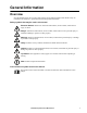
General Information Overview Note the definitions for the icons here and be observant for them throughout this manual. They are intended to call attention to potential hazards and important information. Safety symbols that may be used in this manual Electrical Hazard: Indicates an electrical hazard which, if not avoided, could result in injury or death. Danger: Indicates a hazard which, if not avoided, could result in severe personal injury or substantial damage to product or other property.
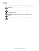
Safety Read and adhere to the following important safety considerations when working with this cooling unit. Note: All work should be performed by American Power Conversion (APC®) authorized personnel only. Caution: Keep your hands, clothing, and jewelry away from moving parts. Check the equipment for foreign objects before closing the doors and starting the equipment. Heavy: The equipment is heavy. For safety purposes, at least two people must be present when moving this equipment.
Commissioning Warning: Procedures in this section must be performed by APC authorized personnel. Electrical Hazard: Perform Lockout/Tagout procedures on the cooling unit before servicing. Failure to remove power before servicing this equipment could result in serious injury or death. After installation, complete the following checklists to verify that all components are working properly and that the equipment is ready to begin operation.
Mechanical inspection The mechanical inspection verifies that all mechanical components and connections are secure. Caution: Failure to properly install piping may result in improper cooling unit operation or possible damage to the cooling unit or surrounding equipment. Ensure that the: R Condensate drain line is at least the size of the drain connection. R Mechanical connections are tight. R Fans are turning freely and the blades are not distorted or bent. R Pipe fittings are tight.
Start-up Inspection The start-up inspection ensures that the equipment is operating properly after the initial start-up. This inspection verifies that all modes of operation are working correctly and that the cooling unit is ready for normal operation. While the equipment is operating, ensure that: R The cooling unit is free from malfunctions, including chilled water leaks, unusual vibrations, or other irregularities, in each mode of operation.
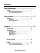
Operation Display Interface ESC S tatus Check Log ? Warnin g na1958a Critical 6 Item Function 1 Critical Alarm LED (red) When lit, a critical alarm condition exists and requires your immediate attention. 2 Warning Alarm LED (yellow) When lit, a warning alarm condition exists. Failure to correct this condition could cause a critical alarm. 3 Check Log LED (yellow) When lit, at least one new event has been logged since the last time the log was checked.
Using the Display Every time you apply power to the cooling unit, the display interface initializes, causing the LEDs to cycle and the alarm-tone to activate. Scrolling status screens After start-up, the interface displays the firmware revision number of the display interface. The display interface then scrolls automatically and continuously through screens of status information. Press the up or down arrow key to interrupt the automatic scrolling and view a specific status screen.
Clear Event Log Configure Modbus Set Date & Time Set Password na1623b Continue arrows. Continue arrows 2 indicate that additional options or settings are available on a menu or status screen. Press the up or down arrow key to view the additional items. Navigating sub-menus Time: 13:15:23 Date: 18-Nov-2006 Format: dd/mm/yyyy na1623c Selecting a main menu option displays the sub-menu screen for that option. In this example, the selector arrow is on the top line of the Set Date and Time sub-menu screen.
Password entry The cooling unit has two levels of password protection: • Device password allows Device Users to change basic and environmental settings. • Admin password allows all privileges granted for Device Users, and also allows the Administrator to modify settings that control the components in the cooling unit or change advanced options. When you try to change a setting, the display interface prompts you to enter your Admin password.
Start the cooling unit Path: Main > On/Standby 1. To start the cooling unit, press the ENTER key until the cursor is on the Operation>On/Standby menu item. 2. Press the ENTER key again to show the toggle state arrow to the right of Operation. 3. Use the up and down arrow keys to change from Standby to On. See “Path: Main > Operation> Limit Access” below if you are prompted to enter a password before changing the On/Standby setting. 4. Press the ENTER key again to set the On position. a.
General Configuration The cooling group configuration options are set during the commissioning of the cooling units in the cooling group. Caution: This procedure is to be performed by APC authorized personnel only. Changing the settings incorrectly can cause malfunctions to your cooling unit. Cooling unit configuration Path: Main > Configure Unit > General Capacity. Set the cooling capacity of the cooling unit: – Auto: The cooling unit automatically controls its output under normal (default) conditions.
Contacts View the state of input and output contacts Path: Main > Configure Unit > Discrete I/O Each cooling unit supports a user-defined input contact and a user-defined output contact. Each contact monitors a sensor and responds to changes in the state of the sensor (open or closed). Input State. Indicates the actual state of the input contact (open or closed). A cooling unit is On when the state is normal and in Standby when the state is not normal. Output State.
%Glycol. The percentage of glycol used by the Cooling Group to cool the environment. Only qualified service personnel should make changes to this setting. Fan Cntrl. This selection allows air flow to be controlled automatically by the cooling unit or maually by user-selected fan speed preference. • Auto: Air flow is automatically controlled by the cooling unit. • Manual: The air flow is fixed to the value of the Fan Speed Preference property. See page 15 for more information Availability.
Control the Environment The primary function of the cooling unit is to cool air from the hot aisle and deliver it to the cold aisle at the temperature setpoint. The control strategies employed by the cooling unit depend upon the deployment strategy of the cooling group. In an in-row environment, the cooling unit supplies constant-temperature supply air to the common cold aisle. The fan speed is modulated to ensure that the desired volume of air reaches the IT equipment.
Setpoints Path: Main > Set Group Setpoints A setpoint is the target value that a cooling group tries to maintain in the rack. The default setpoints are appropriate for most cooling applications. The setpoints for each mode must be within the following ranges: • Cool: 18.0–25.0°C (64.4–77.0°F) • Supply Air: 17.0–23.0°C (62.6–73.4°F) Note: The Supply Air setting is defined when the cooling group is commissioned. This task is performed by APC authorized personnel only.
Tune the PID loop Tune the PID loop to optimize the performance of the cooling group. Caution: This procedure must be performed by APC authorized personnel only. The PID loop must be tuned after the equipment in the room is installed and running. The loop should be tuned periodically to account for changes in the room load. 1.Adjust the integral and derivative constants to zero and the proportional constant to 1.0. 2. Set the temperature setpoint value and start the cooling group. 3.
Run hours The cooling unit records the number of hours each of its components has operated. When a component is replaced, use the Reset Run Hours option to reset the run hours for the displayed component to zero. Path: Main > View Run Hours Components: • Air Filter – Reset Run Hours Note: Replace air filters with APC air filters only. • Fans – Fan Number • Reset Run Hours • Condensate Pump – Reset Run Hours Thresholds Set alarms to alert you to threshold violations.
Display Settings Set display interface settings, including time and date, units, passwords, and time-out. You can also adjust the contrast, key click, beeper volume, and beep on alarm settings. Password & timeout Path: Main > Set Password Note: The default user password is apc (lowercase). See “Password entry” on page 9 for more information on how to enter the password. Change passwords. Set the Admin and Device passwords. 1.
Network Configuration The cooling unit is shipped with a Network Management Card (NMC) that enables you to manage the cooling unit over your network. Configure the network settings for the Network Management Card from the display interface. The management card allows remote control and configuration of the cooling unit . Configure the network Path: Main > Configure Network MAC Address.
View Status Readings The display interface has several options for viewing the status of the cooling unit, the cooling group to which the cooling unit belongs, and the environment being controlled. The status readings for the cooling unit are available under the View Unit Status option in the main menu, and status readings for the cooling group are available under the View Group Status option on the main menu or on the scrolling status screens.
Cooling group status Path: Main > View Group Status View information about the cooling group. Max Rack (Maximum). The highest rack temperature reported by any cooling unit in the cooling group. Min Rack (Minimum). The lowest rack temperature reported by any cooling unit in the cooling group. Air Flow. The combined airflow output of the cooling units in the cooling group. Cool Output. The combined output of the cooling group. Cool Demnd (Demand).
Respond to Alarms When an alarm is triggered, the cooling unit alerts you through the display by the following methods: • Active alarm screen entry on scrolling status screens • LEDs on the front panel display • An optional audible alarm every 30 seconds, if enabled View active alarms Path: Main > View Alarms The View Alarms screen provides the number of alarms, the severity, and a brief description of the alarm. Press the arrow keys to view the rest of the list.
Alarm Message Severity Action Required Entering Fluid Temperature Sensor Fault Warning • Make sure the sensor is connected properly. • If the problem persists, contact APC Customer Support. External Communication Fault Critical • A hardware failure exists. • For assistance, contact APC Customer Support. Fan #n Fault Warning • A hardware failure exists. • For assistance, contact APC Customer Support.
Alarm Message Severity Action Required Return Air High Temperature Violation Warning • Make sure the Return Air threshold is set correctly in the Set Unit Threshlds screen. • If the problem persists, contact APC Customer Support. Return Air Sensor Fault Critical • Make sure the sensor is connected properly. • Replace the sensor. • If the problem persists, contact APC Customer Support. Supply Air High Temperature Violation Warning • Make sure the temperature sensor is connected properly.
Network Management Card Quick Configuration The cooling unit is shipped with a Network Management Card that enables the cooling unit to be managed over a network. Configure the Network Management Card to control this cooling unit through a network. Overview You must configure the following TCP/IP settings before the Network Management Card can operate on a network: • IP address of the Network Management Card • Subnet mask • Default gateway Caution: Never use the loopback address (127.0.0.
4. When the Wizard discovers the unconfigured Network Management Card, follow the on-screen instructions. Note: If you leave the Start a Web browser when finished option enabled, you can use apc for both the user name and password to access the Network Management Card through your browser. .ini file utility You can use the .ini file export utility to export .ini file settings from configured Network Management Cards to one or more unconfigured Network Management Cards.
DHCP. You can use a RFC2131/RFC2132-compliant DHCP server to configure the TCP/IP settings for the Network Management Card. This section summarizes communication between the Network Management Card and a DHCP server. For more detail about how a DHCP server can configure the network settings for a Network Management Card, see “DHCP Configuration” in the User’s Guide. 1.
Remote access to the control console From any computer on the same subnet as the Network Management Card, you can use ARP and Ping to assign an IP address to a Network Management Card, and then use Telnet to access the control console of that Network Management Card and configure the needed TCP/IP settings. Note: After the IP address of the Network Management Card is configured, you can use Telnet without first using ARP and Ping to access that Network Management Card. 1.
Control console After you log on at the control console, as described in“Local access to the control console” on page 27 or “Remote access to the control console” on page 28: 1. Choose Network from the Control Console menu. 2. Choose TCP/IP from the Network menu. 3. If you are not using a BOOTP or DHCP server to configure the TCP/IP settings, select the Boot Mode menu and then select Manual boot mode. 4. Set the System IP, Subnet Mask, and Default Gateway address values.
Access a Configured Network Management Card Overview After the Network Management Card is running on your network, you can access the configured Network Management Card through the following interfaces: • Web interface (HTTP or HTTPS protocol) • Telnet or Secure SHell (SSH) • SNMP • FTP or Secure CoPy (SCP) to upgrade firmware • Modbus For more information on the interfaces, see the User’s Guide. Web interface Use Microsoft® Internet Explorer® (IE) 5.
Telnet and SSH You can access the control console through Telnet or Secure SHell (SSH), depending on which is enabled. Select the Administration tab, the Network option on the top menu bar, and then the access option under Console on the left navigation menu. By default, Telnet is enabled. Enabling SSH automatically disables Telnet. Telnet for basic access. Telnet provides the basic security of authentication by user name and password, but not the high-security benefits of encryption.
Simple Network Management Protocol (SNMP) SNMPv1 only. After you add the PowerNet® MIB to a standard SNMP MIB browser, you can use that browser to access the Network Management Card. All user names, passwords, and community names for SNMP are transferred over the network as plain text. The default read community name is public; the default read/write community name is private. SNMPv3 only. For SNMP GETs, SETs, and trap receivers, SNMPv3 uses a system of user profiles to identify users.
Modbus Modbus lets you view the Network Management Card through the interface of your building management system. The Modbus interface supports 2-wire RS-485, plus ground. Note: Modbus can be configured to run at either 9600 or 19200 bps. It is already configured for 8 data bits, no parity, and 1 stop bit, which are not changeable. To access the Modbus register map, go to the APC Web site, www.apc.com.
Maintenance Monthly Preventive Maintenance Photocopy the following pages and use them during the maintenance procedures. After they have been completed, save them for future reference.
Mechanical Electrical Hazard: Turn off the cooling unit and disconnect all power sources. Perform Lockout/ Tagout procedures before performing any electrical or mechanical service. Wear appropriate personal protective equipment when checking hazardous voltages. Check the fans. All components should be moving freely with no signs of binding or damages. Verify that the condensate line is flowing freely. Electrical Electrical Hazard: Turn off the cooling unit and disconnect all power sources.
Quarterly Preventive Maintenance * Perform all the Monthly Preventive Maintenance items and the items below. Prepared By: _________________________________ Model Number: _______________________________ Serial Number: _______________________________ Date: ______________________________________ Mechanical Electrical Hazard: Turn off the cooling unit and disconnect all power sources. Perform Lockout/Tagout procedures before performing any electrical or mechanical service.
Troubleshooting Problem Possible Cause Corrective Action Controls erratic or inoperative • Inlet temperature to cooling unit is higher than rated maximum temperature • Reduce the load or add additional cooling equipment. Fans fail to start • Cooling unit shutdown due to an external command • Temporarily remove the input contact cable, if it is connected. • Single fan fails to start • Verify that the farn circuit breaker is ON.
Problem Possible Cause Corrective Action Incorrect air pressure • False filter clogs • Verify that the ends of the clear plastic air tubes are not obstructed. • Verify that the clear plastic air tubes are connected to the controller. • Verify that the clear plastic air tubes are not pinched.
APC Worldwide Customer Support Customer support for this or any other APC product is available at no charge in any of the following ways: • Visit the APC Web site to access documents in the APC Knowledge Base and to submit customer support requests. – www.apc.com (Corporate Headquarters) Connect to localized APC Web sites for specific countries, each of which provides customer support information. – www.apc.com/support/ Global support searching APC Knowledge Base and using e-support.