Operation and Maintenance InRow® RD ACRD500 ACRD501 ACRD502
This manual is available in English on the enclosed CD. Dieses Handbuch ist in Deutsch auf der beiliegenden CD-ROM verfügbar. Deze handleiding staat in het Nederlands op de bijgevoegde cd. Este manual está disponible en español en el CD-ROM adjunto. Ce manuel est disponible en français sur le CD-ROM ci-inclus. Questo manuale è disponibile in italiano nel CD-ROM allegato. 本マニュアルの日本語版は同梱の CD-ROM からご覧になれます。 Instrukcja Obsługi w jezyku polskim jest dostepna na CD.
American Power Conversion Legal Disclaimer The information presented in this manual is not warranted by the American Power Conversion Corporation to be authoritative, error free, or complete. This publication is not meant to be a substitute for a detailed operational and site specific development plan.
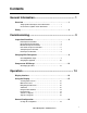
Contents General Information ........................................................ 1 Overview . . . . . . . . . . . . . . . . . . . . . . . . . . . . . . . . . . . . . . . . . . . . . . . . 1 Safety symbols that may be used in this manual . . . . . . . . . . . . . . 1 Cross-reference symbol used in this manual . . . . . . . . . . . . . . . . . 1 Safety . . . . . . . . . . . . . . . . . . . . . . . . . . . . . . . . . . . . . . . . . . . . . . . . . . . 2 Commissioning ..................................
Contacts . . . . . . . . . . . . . . . . . . . . . . . . . . . . . . . . . . . . . . . . . . . . . . . 20 View the state of Input and output contacts . . . . . . . . . . . . . . . . . . 20 Edit the normal state of input and output contacts . . . . . . . . . . . . 20 Cooling Group Configuration . . . . . . . . . . . . . . . . . . . . . . . . . . . . . . 20 Configure the cooling group . . . . . . . . . . . . . . . . . . . . . . . . . . . . . . 20 Identify the cooling unit . . . . . . . . . . . . . . . . . .
Network Management Card .......................................... 34 Quick Configuration . . . . . . . . . . . . . . . . . . . . . . . . . . . . . . . . . . . . . .34 Overview . . . . . . . . . . . . . . . . . . . . . . . . . . . . . . . . . . . . . . . . . . . . . . . 34 TCP/IP configuration methods . . . . . . . . . . . . . . . . . . . . . . . . . . . . . 34 APC Device IP Configuration Wizard . . . . . . . . . . . . . . . . . . . . . . . . 34 .ini file utility . . . . . . . . . . . . . . . . . . . . . .
Troubleshooting ............................................................ 46 Warranty ......................................................................... 48 One-Year Factory Warranty . . . . . . . . . . . . . . . . . . . . . . . . . . . . . . . . 48 Terms of warranty . . . . . . . . . . . . . . . . . . . . . . . . . . . . . . . . . . . . . . . 48 Non-transferable warranty . . . . . . . . . . . . . . . . . . . . . . . . . . . . . . . . 48 Exclusions . . . . . . . . . . . . . . . . . . . . . . . . .
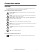
General Information Overview Note the definitions for the icons here and be observant for them throughout this manual. They are intended to call attention to potential hazards and important information. Safety symbols that may be used in this manual Electrical Hazard: Indicates an electrical hazard which, if not avoided, could result in injury or death. Danger: Indicates a hazard which, if not avoided, could result in severe personal injury or substantial damage to product or other property.
Safety Read and adhere to the following important safety considerations when working with this cooling unit. Note: All work should be performed by American Power Conversion (APC®) authorized personnel only. Caution: Keep your hands, clothing, and jewelry away from moving parts. Check the equipment for foreign objects before closing the doors and starting the equipment. Heavy: The equipment is heavy. For safety purposes, at least two people must be present when moving this equipment.
Commissioning Warning: Procedures in this section must be performed by APC authorized personnel. Electrical Hazard: Perform Lockout/Tagout procedures on the cooling unit before servicing. Failure to remove power before servicing this equipment could result in serious injury or death. After installation, verify that all components are working properly and that the equipment is ready to begin operation.
Electrical Inspection Checklist The electrical inspection verifies that all electrical connections are secure and correct and that the equipment is properly grounded. Electrical Hazard: All electrical wiring must comply with local and national codes and regulations. Electrical Hazard: The equipment must be grounded (do not use a water-pipe ground). Electrical Hazard: Three-phase electrical service (plus ground) is required.
Mechanical Inspection Checklist The mechanical inspection verifies that all mechanical components and connections are secure and tight and ready for start-up. The inspection ensures that field piping is properly installed to promote oil return to the compressor. Caution: The equipment is shipped from the factory with a nitrogen holding charge. Remove the nitrogen holding charge using the Schrader valves located on the internal refrigerant piping.
User Interface Inspection Checklist The user interface inspection verifies that the sensors and internal communication links are installed properly. Check that the outdoor heat exchanger is connected to the cooling unit and to the other cooling units in the room if you are using cooling group controls. Ensure that: 6 An A-Link bus is connected to each cooling unit and a terminator is plugged into all unused A-Link connectors. The input contacts and output relays are connected correctly.
Start-up Inspection Checklist The start-up inspection ensures that the equipment is operating properly after the initial start-up. This inspection verifies that all modes of operation are working correctly and that the cooling unit is ready for normal operation. Electrical Hazard: Perform Lockout/Tagout procedures on the cooling unit before servicing. Failure to remove power before servicing this equipment could result in serious injury or death.
Final Inspection Checklist The final inspection verifies that the system is clean, the installed options work properly, and the start-up form is sent to APC. Ensure that: 8 The system is clean and free of debris. Packaging materials are disposed of properly. The start-up form was completed and sent to APC.
Charging With Refrigerant Calculating R407C charge Use the following table and formula when calculating the total R407C charge. Condenser model LNE-S01-A009 APC SKU ACCD75201 ACCD75204 LNE-S02-A015 ACCD75202 ACCD75205 LNE-S03-A027 ACCD75203 ACCD75206 KH1180.BDVES ACCD75207 KH1280.ADVES ACCD75208 KH1280.CDVES ACCD75209 Selected Condenser ambient summer temp.
Charging the equipment Caution: This procedure is to be done by APC-trained personnel only. R407C is a blend refrigerant. When charging equipment with blend refrigerants, only liquid refrigerant must be charged. Caution: Charging with other than liquid R407C refrigerant may damage the system. 1. Ensure the ball valves are open. Service port 2. Confirm the calculated system charge. Schrader port na2455a 3. Connect the refrigerant cylinder to the charging or gauge port on the receiver outlet valve.
8. Charge the rest of the calculated liquid refrigerant very slowly through the suction port. Caution: Fast charge of liquid refrigerant through the suction port may damage the compressor. 9. Verify that the sightglass is clear. If there is excessive bubbling in the sightglass, make sure the system high side pressure is above 15.9 bar (230 psi) and Superheat and Subcooling are within parameters (10-12 for Superheat and 8-10 for Subcooling).
Compressor Oil Charge Caution: This procedure is to be done by APC-trained personnel only. You may need to add oil to air-cooled equipment, depending on the condenser size and the lengths of tube running between the equipment and the condenser. Let the compressor run at full capacity for at least one hour and check the oil level in the oil sight glass. The level should be between 1/4 and 3/4 full, or within the limit shown on the oil level sticker.
3. Purge the pump and hose: a. Ensure that the oil pump is clean. Insert the pump in the oil container and make sure that the container is open to the atmosphere for as short a period of time as possible. When available, use a plug adaptor kit to further reduce the exposure of the oil to the atmosphere. b. Bleed all air from the pump and hose with a few strokes of the pump. Purging the pump removes the moisture-saturated oil left inside the hose from previous usage. c.
Operation Display Interface S tatus ESC Check Log ? Warnin g na1958a Critical 14 Item Function 1 Critical Alarm LED (red) When lit, a critical alarm condition exists and requires your immediate attention. 2 Warning Alarm LED (yellow) When lit, a warning alarm condition exists. Failure to correct this condition could cause a critical alarm. 3 Check Log LED (yellow) When lit, at least one new event has been logged since the last time the log was checked.
Using the Display Every time you apply power to the cooling unit, the display interface initializes, causing the LEDs to cycle and the alarm-tone to activate. Scrolling status screens After start-up, the interface displays the firmware revision number of the display interface. The display interface then scrolls automatically and continuously through screens of status information.
Navigating the main menu Clear Event Log Configure Modbus Set Date & Time Set Password na1623d Selector arrow. Press the up or down arrow key to move the selector arrow to a main menu option. Press the ENTER key to view the selected sub-menu screen. In the example shown below, the selector arrow points to the Set Date and Time setting. To select that item, press the ENTER key.
Using the Path statement Select the main- and sub-menu options specified in the path statement to view or configure a setting. The path statement lists the main- and sub-menu items you select to navigate to the item to view or modify. The parts of the path statement are defined below: Path: Main > Set Password >Change Passwords Main >Your starting point is the main menu. Set Password > Scroll to and select this option from the main menu. Change Passwords > Scroll to and select this option from the sub-menu.
Start the cooling unit Path: Main > On/Standby To start the cooling unit, change the setting to On by pressing the ENTER key to toggle from Standby to On. At that point, the fans will start. The cooling unit will run according to the configured settings. Note: On/Standby only affects the local cooling unit. You must set the On/Standby option for each cooling unit in the cooling group.
General Configuration The cooling group configuration options are set during the commissioning of the cooling units in the cooling group. Caution: This procedure is to be performed by APC authorized personnel only. Changing the settings incorrectly can cause malfunctions to your cooling unit. Cooling unit configuration Path: Main > Configure Unit > General Capacity. Set the cooling capacity of the cooling unit: – Auto: The cooling unit automatically controls its output under normal (default) conditions.
Contacts View the state of Input and output contacts Path: Main > Configure Unit > Discrete I/O Each cooling unit supports a user-defined input contact and a user-defined output contact. Each contact monitors a sensor and responds to changes in the state of the sensor (open or closed). Input State. Indicates the actual state of the input contact (open or closed). A cooling unit is On when the state is normal and in Standby when the state is not normal. Output State.
Type. Set the rack deployment strategy for the cooling units of this cooling group. • In-Row: Air flow is not ducted. Hot aisle air is cooled, then shared by all loads in the row. • RACS: (Rack Air Containment System). Air flow in the enclosure is controlled by a ducting system fitted to the enclosure. • HACS: (Hot Aisle Containment System). Air flow in the room is controlled by enclosing the hot air aisle. The loads share an enclosed common hot aisle.
Control the Environment The primary function of the cooling unit is to cool air from the hot aisle and deliver it to the cold aisle at the temperature setpoint. The control strategies employed by the cooling unit depend upon the deployment strategy of the cooling group. In an InRow environment, the cooling unit supplies constant-temperature supply air to the common cold aisle. The fan speed is modulated to ensure that the desired volume of air reaches the IT equipment.
• Fan Spd: .Set the fan speed preference that will give you the desired temperature difference (DT). Each fan speed provides an approximate DT between the supply air from the equipment and the air returned from the rack. – Low = 16.7°C (30°F) DT – Med-Low = 13.9°C (25°F) DT – Med = 11.1°C (20°F) DT – Med-High = 6.3°C (15°F) DT – High = 5.6°C (10°F) DT Note: The cooling group will automatically override this fan speed setting and adjust the fan speed to provide optimum cooling for the environment as needed.
Tune the PID loop Tune the PID loop to optimize the performance of the cooling group. Caution: This procedure must be performed by APC authorized personnel only. The PID loop must be tuned after the equipment in the room is installed and running. The loop should be tuned periodically to account for changes in the room load. 1. Adjust the integral and derivative constants to zero and the proportional constant to 1.0. 2. Set the temperature setpoint value and start the cooling group. 3.
Run hours The cooling unit records the number of hours each of its components has operated. When a component is replaced, use the Reset Run Hours option to reset the run hours for the displayed component to zero. Path: Main > View Run Hours Components: • Air Filter – Reset Run Hours Note: Replace air filters with APC air filters only. • Fans – Fan Number • Reset Run Hours • Condensate Pump – Reset Run Hours • Compressor – Reset Run Hours Thresholds Set alarms to alert you to threshold violations.
Display Set display interface settings, including time and date, units, passwords, and time-out. You can also adjust the contrast, key click, beeper volume, and beep-on-alarm settings. Password and timeout Path: Main > Set Password Note: The default user password is apc (lowercase). See “Password entry” on page 17 for more information on how to enter the password. Change passwords. Set the Admin and Device passwords. 1. Move the selector arrow next to the Change Passwords option and press the ENTER key.
Adjust display Path: Main Menu >Configure Display Contrast. Adjust the visibility of the screen text. Lower numbered settings provide darker text; higher numbers provide lighter text. Settings range from 0–7. Key Click. Enable or disable an audible tone every time a key is pressed on the display interface. Beeper Volume. Set the volume of the display interface alarm tone, and for the audible tone that sounds every time a key is pressed on the display interface. Beep On Alarm.
Network Configuration The cooling unit is shipped with a Network Management Card (NMC) that enables you to manage the cooling unit over your network. Configure the network settings for the equipment Network Management Card from the display interface. The management card allows remote control and configuration of the equipment. Configure the network Path: Main > Configure Network MAC Address.
View Status Readings The display interface has several options for viewing the status of the cooling unit, the cooling group to which the cooling unit belongs, and the environment being controlled. The status readings for the cooling unit are available under the View Unit Status option in the main menu, and status readings for the cooling group are available under the View Group Status option on the main menu or on the scrolling status screens.
Compressor Drive: Voltage. The compressor voltage. Compressor Drive: Current. The compressor current draw. Compressor Drive: DC Link. The compressor internal direct current (DC) link voltage. Compressor Drive: Heat Sink. The compressor heat sink temperature. Compressor Drive: Ctrl Card (Control Card). The compressor control card temperature. Compressor Drive: Warn Stat. The compressor warning word used for diagnostics. Compressor Drive: Alrm Stat. The compressor alarm word used for diagnostics.
Event Log The event log saves status information and a message each time a change in the cooling group is detected. Alarms and events are recorded in the log and displayed on the active alarms screen. Status events (informational) and system configuration changes are only displayed in the event log. View event log Path: Main > View Event Log The event log keeps a record of all alarms and events. The screen displays the following: • The name of the event. • The time and date the event occurred.
Alarm messages and suggested actions Alarm Message Severity Action Required Air Containment Pressure Sensor Fault Warning • A hardware failure exists. For assistance, contact APC at a number listed on the back cover of this manual. Air Filter Clogged Warning • Clean or replace the air filter. • If the problem persists, contact APC at a number listed on the back cover of this manual.
Alarm Message Severity Action Required Persistant High Discharge Pressure Fault Critical • Indicates there were three High Discharge Pressure shutdowns in 30 minutes. Alarms must be cleared manually. • If the problem persists, contact APC at a number listed on the back cover of this manual. High Suction Pressure Fault Warning • Check the air filter and evaporator for obstructions. • If the problem persists, contact APC at a number listed on the back cover of this manual.
Network Management Card Quick Configuration The cooling unit is shipped with a Network Management Card that enables the cooling unit to be managed over a network. Configure the Network Management Card to control this cooling unit through a network. Overview You must configure the following TCP/IP settings before the Network Management Card can operate on a network: • IP address of the Network Management Card • Subnet mask • Default gateway Caution: Never use the loopback address (127.0.0.
2. If autorun is enabled, the user interface of the CD starts when you insert the CD. If autorun is not enabled, open the file contents.htm on the CD. 3. Select the Device IP Configuration Wizard from the main menu. 4. When the Wizard discovers the unconfigured Network Management Card, follow the on-screen instructions. Note: If you leave the Start a Web browser when finished option enabled, you can use apc for both the user name and password to access the Network Management Card through your browser. .
DHCP. You can use a RFC2131/RFC2132-compliant DHCP server to configure the TCP/IP settings for the Network Management Card. This section summarizes communication between the Network Management Card and a DHCP server. For more detail about how a DHCP server can configure the network settings for a Network Management Card, see “DHCP Configuration” in the User’s Guide. 1.
Remote access to the control console From any computer on the same subnet as the Network Management Card, you can use ARP and Ping to assign an IP address to a Network Management Card, and then use Telnet to access the control console of that Network Management Card and configure the needed TCP/IP settings. Note: After the IP address of the Network Management Card is configured, you can use Telnet without first using ARP and Ping to access that Network Management Card. 1.
Control console After you log on at the control console, as described in“Local access to the control console” on page 36 or “Remote access to the control console” on page 37: 1. Choose Network from the Control Console menu. 2. Choose TCP/IP from the Network menu. 3. If you are not using a BOOTP or DHCP server to configure the TCP/IP settings, select the Boot Mode menu and then select Manual boot mode. 4. Set the System IP, Subnet Mask, and Default Gateway address values.
Access a Configured Network Management Card Overview After the Network Management Card is running on your network, you can access the configured Network Management Card through the following interfaces: • Web interface (HTTP or HTTPS protocol) • Telnet or Secure SHell (SSH) • SNMP • FTP or Secure CoPy (SCP) to upgrade firmware • Modbus For more information on the interfaces, see the User’s Guide. Web interface Use Microsoft® Internet Explorer® (IE) 5.
Telnet for basic access. Telnet provides the basic security of authentication by user name and password, but not the high-security benefits of encryption. To use Telnet to access the control console of the Network Management Card: 1. At a command prompt, use the following command line, and press ENTER: telnet address As address, use the IP address of the Network Management Card or DNS name (if configured). 2.
FTP/SCP You can use FTP (enabled by default) or Secure CoPy (SCP) to transfer downloaded firmware to the Network Management Card, or to access a copy of the event or data logs of the cooling unit. SCP provides the higher security of encrypted data transmission and is enabled automatically when you enable SSH. To use InfraStruXure Manager to manage the Network Management Card, you must have the FTP Server enabled in the Network Management Card.
Recover From a Lost Password You can use a local computer (a computer that connects to the Network Management Card through the serial port) to access the control console. 1. Select a serial port at the local computer, and disable any service that uses that port. 2. Connect the provided RS-232 configuration cable to the selected port on the computer and to the RS-232 console port at the Network Management Card. 3.
Maintenance Monthly Preventive Maintenance Photocopy the following pages and use them during the maintenance procedures. After they have been completed, save them for future reference.
Mechanical Electrical Hazard: Turn off the cooling unit and disconnect all power sources. Perform Lockout/ Tagout procedures before performing any electrical or mechanical service. Wear appropriate personal protective equipment when checking hazardous voltages. Check the fans. All components should be moving freely with no signs of binding or damages. Verify that the condensate line is flowing freely. Electrical Electrical Hazard: Turn off the cooling unit and disconnect all power sources.
Quarterly Preventive Maintenance * Perform all the Monthly Preventive Maintenance items and the items below. Prepared By: _________________________________ Model Number: _______________________________ Serial Number: _______________________________ Date: ______________________________________ Mechanical Electrical Hazard: Turn off the cooling unit and disconnect all power sources. Perform Lockout/ Tagout procedures before performing any electrical or mechanical service.
Troubleshooting Problem Possible Cause Corrective Action Controls erratic or inoperative • Inlet temperature to cooling unit is higher than rated maximum temperature • Reduce the load or add additional cooling equipment. Fans fail to start • Cooling unit shutdown due to an external command • Temporarily remove the input contact cable, if it is connected. • Single fan fails to start • Verify that the farn circuit breaker is ON.
Problem Possible Cause Corrective Action Alarms do not show up on monitoring equipment (Customer Output Contact) • External monitoring equipment is not receiving power or is not functioning properly • Confirm that power, if required, is being supplied to the external equipment. • If the cooling unit (+12 V or +24 V) is providing power to the external equipment, verify that the external equipment is <50 mA. • Test the external equipment by bypassing the customer output contact.
Warranty One-Year Factory Warranty The limited warranty provided by American Power Conversion (APC®) in this Statement of Limited Factory Warranty applies only to products you purchase for your commercial or industrial use in the ordinary course of your business. Terms of warranty American Power Conversion warrants its products to be free from defects in materials and workmanship for a period of one year from the date of purchase.
IN NO EVENT SHALL APC, ITS OFFICERS, DIRECTORS, AFFILIATES OR EMPLOYEES BE LIABLE FOR ANY FORM OF INDIRECT, SPECIAL, CONSEQUENTIAL OR PUNITIVE DAMAGES, ARISING OUT OF THE USE, SERVICE OR INSTALLATION, OF THE PRODUCTS, WHETHER SUCH DAMAGES ARISE IN CONTRACT OR TORT, IRRESPECTIVE OF FAULT, NEGLIGENCE OR STRICT LIABILITY OR WHETHER APC HAS BEEN ADVISED IN ADVANCE OF THE POSSIBILITY OF SUCH DAMAGES.
Warranty Procedures Claims To obtain service under the warranty, contact APC Customer Support (see the back cover of this manual for contact information). You will need the model number of the Product, the serial number, and the date purchased. A technician will also ask you to describe the problem. If it is determined that the Product will need to be returned to APC, you must obtain a returned material authorization (RMA) number from APC Customer Support.
APC Worldwide Customer Support Customer support for this or any other APC product is available at no charge in any of the following ways: • Visit the APC Web site to access documents in the APC Knowledge Base and to submit customer support requests. – www.apc.com (Corporate Headquarters) Connect to localized APC Web sites for specific countries, each of which provides customer support information. – www.apc.com/support/ Global support searching APC Knowledge Base and using e-support.