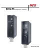
® Chilled Water/Direct Expansion — 50/60 Hz AIR-COOLED ACRP100 ACRP101 ACRP102 CHILLED WATER ACRP500 ACRP501 ACRP502 Technical Data
American Power Conversion Legal Disclaimer The information presented in this manual is not warranted by the American Power Conversion Corporation to be authoritative, error free, or complete. This publication is not meant to be a substitute for a detailed operational and site specific development plan.
Contents Overview .......................................................................... 1 Capacity . . . . . . . . . . . . . . . . . . . . . . . . . . . . . . . . . . . . . . . . . . . . 1 Room Air Distribution . . . . . . . . . . . . . . . . . . . . . . . . . . . . . . . . . 1 Configuration . . . . . . . . . . . . . . . . . . . . . . . . . . . . . . . . . . . . . . . . 1 Compliance Approval . . . . . . . . . . . . . . . . . . . . . . . . . . . . . . . . . . 1 Chilled Water Standard Features . . . . .
Optional Features ............................................................ 6 Cable Water Detector . . . . . . . . . . . . . . . . . . . . . . . . . . . . . . . . . .6 Network Cable . . . . . . . . . . . . . . . . . . . . . . . . . . . . . . . . . . . . . . .6 85% ASHRAE 52.1 Filter . . . . . . . . . . . . . . . . . . . . . . . . . . . . . . . .6 Power Trough . . . . . . . . . . . . . . . . . . . . . . . . . . . . . . . . . . . . . . .6 Data Partition . . . . . . . . . . . . . . . . . . . . . . . . . . .
Dimensional Data........................................................... 28 InRow RP Assembled Module . . . . . . . . . . . . . . . . . . . . . . . . . . 28 SX to VX Height Adapter . . . . . . . . . . . . . . . . . . . . . . . . . . . . . . 29 SX to 48U SX Height Adapter . . . . . . . . . . . . . . . . . . . . . . . . . . . 29 Piping and Mechanical Connections ........................... 30 Chilled water piping diagram . . . . . . . . . . . . . . . . . . . . . . . . . . .
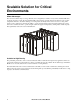
Overview The modular, row-based computer room cooling system offers efficient, predictable, and economical cooling for a variety of spaces. Configuration Critical environmental requirements now reach far beyond the confines of the traditional data center or computer room to encompass a larger suite of applications, referred to as technology rooms.
Scalable Solution for Critical Environments InRow Advantages The row-based solution improves energy efficiency and cooling ability in a number of ways. First, the InRow RP draws air directly from the hot aisle, allowing the InRow RP to take advantage of higher heat transfer efficiency due to higher temperature differences. It can then discharge room temperature air directly in front of the servers it is cooling.
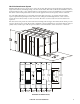
Hot Aisle Containment System Modular ceiling tiles and doors can be used to enclose the hot aisle. This increases the densities that can be handled in a single rack enclosure by eliminating mixing of hot and cold air streams. This method, called load neutralization, removes the heat from the hot aisle, cools it, and then returns it to the surrounding room area at or slightly below room temperature.
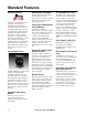
Standard Features Insulated Cabinet The frame is constructed of 1.5 mm (16 gauge) formed steel for maximum strength. Cabinet is serviceable from the front and rear. All exterior panels and corner posts on the frame are powder coated for durability and an attractive finish. Front and rear exterior panel are constructed of 1.2 mm (18 gauge) perforated steel with 69.5% open free area. Insulation is 80.1 kg/m3 (5 lb/ft3) density and complies with ASTM E84 rating of 25/50.
Dual Position Float Condensate Management Bay Kit InRow RP/ NetShelter SX The pump is factory wired and piped internally to the condensate drain pan and humidifier outlet. The pump is capable of pumping a maximum of 18 m (60 ft) at 0.009 l/s (8.45 GPH), which may include a maximum lift of 3.5 m (11.5 ft) of head. A dual position float is included with the unit.
Optional Features Cable Water Detector 85% ASHRAE 52.1 Filter Data Partition A leak detection cable is placed on the floor or subfloor around all possible leak sources. If water or other conductive liquids contact the cable anywhere along its length, the microprocessor controller announces the leak visually, audibly, and across the network. The 6.1 m (20 ft) cable may be cascaded to make custom lengths up to 24.4 m (80 ft).
Microprocessor Controller Status ESC Check Log ? Warning Critical Alarm LED Warning Alarm LED Check Log LED Status LED Liquid Crystal Display (LCD) Menu Selection scroll keys Escape key Enter key Help key Critical Microprocessor Controller Control Type Logging The microprocessor controller is standard on each system.
Alarms The microprocessor controller shall activate a visible and audible alarm in the following occurrences: • Cool Fail • Rack inlet temperature violation • Rack inlet temperature sensor fault • Air filter clogged • Air filter run hours exceeded • Filter DP sensor failure Chilled Water Only Alarms • Coil fluid valve actuator fault • High discharge pressure • Fluid flow fault • Low suction pressure • Entering fluid temperature high violation • High suction pressure • Entering fluid temperature senso
InRow RP Models Hinged rear doors Casters (all swiveling) Side panel lock Door handle and lock Removable side panel Display interface Adjustable leveling foot Hinged front door InRow RP Technical Data Manual 9
na2090a Chilled water interior components (front of unit) 10 Electric heater (for reheat) Electrical panel Fan Supply temperature sensors Fan guard Main feed breakers Humidifier Ladder diagrams Condensate drain pan User interface connectors Condensate pump Supply humidity sensor InRow RP Technical Data Manual
na2105a Chilled water interior components (back of unit) Chilled water coil Rear doors Chilled water control actuator Air filters Chilled water three-way valve body Return humidity sensor Flow meter Return temperature sensor Pipe chase InRow RP Technical Data Manual 11
na2070a Air-cooled interior components (front of unit) 12 Electric heater (for reheat) Main circuit breaker Condensate drain pan Fan Thermal expansion valve Fan guard Receiver Electrical panel Compressor Ladder diagrams Variable Frequency Drive (for compressor) Communication and external device connectors Supply air temperature sensor Humidity sensor InRow RP Technical Data Manual
na2074a Air-cooled interior components (back of unit) Evaporator coil Shutoff valves (top piping only) Condensate drain pan Air filters Sight glass Pipe chase Filter dryer Humidity sensor Condensate pump Return air temperature sensor Humidifier InRow RP Technical Data Manual 13
Chilled water and air-cooled user interface connections Rack inlet temperature sensors 1, 2, 3 A-Link IN A-Link OUT Network port Console port Alarm output, NC (Normally Closed) Alarm output, COM (Common) Alarm output, NO (Normally Open) Supply GND (Ground) Supply 12 Vdc (current limit: 20 mA) Supply 24 Vdc (current limit: 20 mA) Customer input + (12–30 Vac/Vdc, 24 Vdc @ 11 mA) Supply COM BMS D1 (RXTX+) BMS D0 (RXTX–) BMS GND Supply air temp
Chilled water electrical panel Note: ACRP 501 shown.
Air-cooled electrical panel Note: ACRP 101 shown.
Performance Specifications Chilled Water Performance Specifications 5.5°C (42°F) EWT Sensible Net Capacity kW (BTU/hr) Sensible Heat Ratio SHR CW Flow Rate l/s (GPM) Total CW Pressure Drop kPa (ft H2O)* 44.3 (151,000) 40.8 (139,000) 37.8 (129,000) 34.6 (118,000) 31.8 (109,000) 40.7 (139,000) 37.9 (129,000) 35.2 (120,000) 32.5 (111,000) 29.9 (102,000) 0.92 0.93 0.93 0.94 0.94 1.6 (25.9) 1.3 (20.6) 1.1 (16.8) 0.9 (13.8) 0.7 (11.5) 66 (21.95) 42 (14.1) 29 (9.5) 19 (6.5) 14 (4.6) 50.8 (174,000) 47.
Chilled Water Performance Specifications 7.2°C (45°F) EWT Sensible Net Capacity kW (BTU/hr) Sensible Heat Ratio SHR CW Flow Rate l/s (GPM) Total CW Pressure Drop kPa (ft H2O)* 40.8 (139,000) 37.9 (130,000) 35.1 (120,000) 32.5 (111,000) 29.8 (102,000) 27.3 (93,000) 39.6 (135,000) 36.8 (126,000) 34.1 (116,000) 31.5 (108,000) 28.9 (99,000) 26.5 (90,000) 0.97 0.97 0.97 0.97 0.97 0.97 1.8 (28.8) 1.4 (22.5) 1.1 (18.0) 0.9 (14.6) 0.8 (12.0) 0.6 (10.0) 81 (27.03) 50 (16.6) 32 (10.9) 22 (7.4) 15 (5.1) 11 (3.
Chilled Water Performance Specifications 8.9°C (48°F) EWT ( Sensible Net Capacity kW (BTU/hr) Sensible Heat Ratio SHR CW Flow Rate l/s (GPM) Total CW Pressure Drop kPa (ft H2O)* 35.7 (122,000) 32.9 (112,000) 30.3 (103,000) 27.7 (95,000) 25.3 (86,000) 22.7 (78,000) 34.6 (118,000) 31.9 (109,000) 29.4 (100,000) 26.9 (92,000) 24.5 (84,000) 22.3 (76,000) 0.97 0.97 0.97 0.97 0.97 0.98 1.6 (25.5) 1.2 (19.7) 1.0 (15.7) 0.8 (12.7) 0.7 (10.4) 0.5 (8.5) 63 (21.3) 39 (12.9) 25 (8.3) 17 (5.5) 11 (3.9) 8 (2.
Chilled Water Performance Specifications 10°C (50°F) EWT Total Net Temperature dry bulb CW Delta T Capacity (DB), wet bulb (WB) °C (°F) kW (BTU/hr) °C (°F) 26.7°C DB, 17.1°C WB (80°F DB, 62.8°F WB) 5.5 (10) 6.6 (12) 7.7 (14) 8.8 (16) 10 (18) 11.1 (20) 32.6 (111,000) 29.9 (102,000) 27.4 (93,000) 24.9 (85,000) 22.6 (77,000) 20.4 (70,000) Sensible Net Capacity kW (BTU/hr) Sensible Heat Ratio SHR CW Flow Rate l/s (GPM) Total CW Pressure Drop kPa (ft H2O)* 31.8 (109,000) 29.2 (100,000) 26.7 (91,000) 24.
Chilled Water Performance Specifications 12.8°C (55°F) EWT Sensible Net Capacity kW (BTU/hr) Sensible Heat Ratio SHR CW Flow Rate l/s (GPM) Total CW Pressure Drop kPa (ft H2O)* 24.7 (85,000) 22.3 (76,000) 20.0 (68,000) 17.8 (61,000) 15.8 (54,000) 13.9 (48,000) 24.7 (85,000) 22.3 (76,000) 20.0 (68,000) 17.8 (61,000) 15.8 (54,000) 13.9 (48,000) 1.00 1.00 1.00 1.00 1.00 1.00 1.2 (18.3) 0.9 (13.9) 0.7 (10.8) 0.5 (8.6) 0.4 (6.9) 0.4 (5.6) 33 (11.3) 20 (6.7) 12 (4.2) 8 (2.8) 5 (1.8) 4 (1.2) 31.
Chilled Water Performance Specifications 15.5°C (60°F) EWT Sensible Net Capacity kW (BTU/hr) Sensible Heat Ratio SHR CW Flow Rate l/s (GPM) Total CW Pressure Drop kPa (ft H2O)* 17.5 (60,000) 15.2 (52,000) 13.1 (45,000) 11.1 (38,000) 9.3 (32,000) 7.7 (26,000) 17.5 (60,000) 15.2 (52,000) 13.1 (45,000) 11.1 (38,000) 9.3 (32,000) 7.7 (26,000) 1.00 1.00 1.00 1.00 1.00 1.00 0.9 (13.5) 0.6 (10.0) 0.5 (7.6) 0.4 (5.8) 0.3 (4.5) 0.2 (3.5) 19 (6.2) 11 (3.7) 6 (2.1) 4 (1.4) 3 (0.9) 2 (0.5) 23.8 (81,000) 21.
Chilled Water Data - General MODEL MODULATING VALVES ACRP 500 Series Size -3 Way Ball Valve - NPT mm (in) 25.4 (1) AIR SYSTEM - FANS (Standard Filter Installed) Air Volume - l/s (SCFM) Fan Motor - W (HP) Number of Fans 3162 (6700) 1100 (1.5) 3 COOLING COIL - COPPER TUBE/ALUMINUM FIN Face Area - m2 (ft2) Rows Deep Fins per meter (Fins per inch) 0.74 (7.9) 4 468 (12) HUMIDIFICATION - SOLID STATE ELECTRODE CANISTER Flush Cycle Capacity - kg/hr (lbs/hr) kW Automatic 3.0 (6.6) 2.
Glycol Correction Factors Performance Criteria Glycol Solution 0 10% 20% 30% 40% 50% Capacity* Ethylene 1.00 0.97 0.93 0.88 0.81 0.75 Propylene 1.00 0.96 0.90 0.82 0.77 0.74 Ethylene 1.00 1.04 1.13 1.21 1.31 1.41 Propylene 1.00 1.09 1.20 1.35 1.52 1.67 Pressure Drop** Percent Weight of Solution *** All correction factors are based on unit entering conditions of 29.4°C (85°F) DB, 18.1 °C (64.5°F) WB, 1368.6 L/S (6950 CFM), 1.72 L/S (27.3 GPM), and 7.2°C (45°F) EFT.
Air-cooled Data - General MODEL AIR SYSTEM - FAN (Standard Filter Installed) Air Volume - l/s (SCFM) Fan Motor - W (HP) Number of Fans ACRP 100 Series 2265 (4800) 1100 (1.5) 2 COOLING COIL - COPPER TUBE/ALUMINUM FIN Face Area - m2 (ft2) Rows Deep .56 (6.0) 4 HUMIDIFICATION - SOLID STATE ELECTRODE CANISTER Flush Cycle Capacity - kg/hr (lbs/hr) kW automatic 3 (6.6) 2.
Sound Performance Data Chilled Water Tested Sound Data Fan Speed% Sound Power dB at Frequency Hz re: 10-12W Airflow m3/s (SCFM) Lp Sound Pressure dB re: 20 microPa* 125 250 500 1000 2000 4000 8000 dBA dBA 35 1.13 (2500) 69.5 37.5 63.5 60.0 54.0 47.5 40.0 65.4 54.9 50 1.79 (3800) 84.0 79.0 75.5 69.5 67.5 58.5 53.5 76.9 66.8 70 2.55 (5400) 92.0 87.0 83.5 79.0 74.5 69.5 63.5 85.9 75.0 85 3.04 (6450) 92.0 95.0 89.0 84.5 79.0 74.5 69.0 90.6 80.7 100 3.
Electrical Data SKU Voltage MCA MOP LRA RLA FLA Hz Power (kW) ACRP100 200 - 240 80.1 100 160* 50.0 N/A 50/60 19 ACRP101 460 - 480 39.9 50 139* 23.2 N/A 60 21 ACRP102 380 - 415 N/A N/A 139* 23.2 32* 50 20 ACRP500 200 - 240 46.8 50 N/A N/A N/A 50/60 14 ACRP501 460 - 480 24.
Dimensional Data na2465a InRow RP Assembled Module Dimensions are shown in mm (in).
na2445a SX to VX Height Adapter na2446a SX to 48U SX Height Adapter Dimensions are shown in mm (in).
Piping and Mechanical Connections Chilled water piping diagram InRow RP Bottom piping InRow RP Return Supply Top piping Supply Return InRow RP na2572a InRow RP Flex hose or copper Circuit setter (field-installed) Copper tubing Hose end drain with cap Y-strainer with 20 mesh screen (field installed)* Isolation valve *Blow down may be installed on Y-strainer.
Note: Top or bottom entry can be chosen individually for each type of connection, i.e. power, condensate drain, humidifier water supply, chilled water supply and chilled water return. Top piping configuration will have the same valves and strainers as bottom piping configuration. Top chilled water piping access (top view) 554 (21.81) 554 (21.81) 59 (2.32) 40 (1.58) 59 (2.32) 112 (4.4) 0 na2274a 177 (6.97) 737 (29.02) 635 (24.99) 380 (14.98) 325 (12.81) 0 160 (6.3) 73 (2.86 ) 105 (4.12) 40 (1.
Bottom chilled water piping access (bottom view, looking up) 345 (13.58) 796 (31.34) 172 (6.77) 138 (5.43) 345 (13.58) 397 (15.63) 184 (7.24) 187 (7.35) 425 (16.72) 0 0 479 (18.86) REAR—HOT AISLE 141 (5.54) 57.25 (2.25) 176 (6.91) FRONT—COLD AISLE 32 Dimensions are shown in mm (in). Humidifier supply Condensate drain Power connections—dual feed Communication connections—27.80 mm (1.
Air-cooled piping diagram Hot gas Top piping Condenser Liquid Liquid Condenser na2543a Hot gas Bottom piping RP Receiver Receiver RP Note: Shutoff valves shown nearest to the condensers are not supplied by APC. Pitch in direction of refrigerant flow; 4 mm per m (0.5-in per 10 ft) Pressure relief valve Shutoff valves P-trap Head pressure control valve S-trap Check valve Inverted P-trap All lines are Type L copper tubing. Note: Route piping through the top or bottom of the InRow RP.
Air-cooled piping access (top) 547 (21.54) 75 (2.95) 325 (12.78) 73 (2.86) REAR—HOT AISLE 47 (1.85) FRONT—COLD AISLE Refrigerant discharge line Refrigerant liquid line Pressure relief valve discharge line Trough for communication cables Power connections Humidifier water supply Condensate drain Dimensions are shown in mm (in). 34 InRow RP Technical Data Manual 123 (4.84) 558 (21.97) na2071a 738 (29.04) 380 (14.94) 105 (4.12) 40 (1.
345 (13.58) 172 (6.77) 138 (5.43) 345 (13.58) 397 (15.63) 184 (7.24) 796 (31.34) 425 (16.72) 187 (7.35) REAR—HOT AISLE 0 0 479 (18.86) Air-cooled piping access (bottom view, looking up) 156 (6.13) na2072a 115 (4.53) 141 (5.54) FRONT—COLD AISLE 57.25 (2.25) 176 (6.91) Humidifier water supply Condensate drain Power connections Communication connections—27.80 mm (1.09 in) Condensate overflow—50.00 mm (1.
Air-Cooled Condensers Mechanical Data SKU Sounds Pressure Sound (dbA) at 10 ft Pressure set area level, Ambient (dbA) at 10 and Max Temp ft and Compressor 100% Fan Speed Speed Selected Ambient Temp Air Quantity Fan Unit l/s (CFM) Qty. Connection Size Weight Capacity kW Hot Gas Liquid Kg (Lbs) MBH/1F TD kW/1C TD ACCD75201 95 (35) 67 62 4955 (10500) 1 2.2 1 3/8 in 1 3/8 in 163 (360) 8.8 4.6 ACCD75202 105 (40) 70 65 10383 (22000) 2 4.4 1 5/8 in 1 5/8 in 290 (640) 14.6 7.
na2449a ACCD75201 and ACCD75204 na2450a ACCD75202 and ACCD75205 na2051a ACCD75203 and ACCD75206 Dimensions are shown in mm (in). All condensers shown on this page have eight 22 mm (0.875 in) mounting holes on their lower rails.
na2452a ACCD75207 na2453a ACCD75208 and ACCD75209 Dimensions are shown in mm (in). All condensers shown on this page have 16 mm (0.63 in) mounting holes on each of their lower legs. Air-cooled Condenser Features Available in one to three fan configurations, APC offers air-cooled condensers with a vertical air discharge pattern. These condensers utilize variable speed EC motor technology for improved sound and energy performance.
Guide Specifications PART 1 — GENERAL 1.01 SUMMARY A. The environmental control system shall be designed specifically for precision temperature and humidity control applications. It will automatically monitor and control heating, cooling, humidifying, dehumidifying, and filtering functions for the conditioned space.
PART 2 — PRODUCT 2.01 STANDARD COMPONENTS A. CABINET CONSTRUCTION 1 . Exterior panels shall be 1.2 mm (18 gauge) steel. Front and rear exterior panels shall be 1.2 mm (18 gauge) perforated steel with 69.5% open free area, and equipped with a keyed lock to provide a means of securing access to the internal components of the unit. 2 . The frame shall be constructed of 1.5 mm (16 gauge) formed steel welded for maximum strength.
D. MAIN DISCONNECT SWITCH 1 . Unit shall be provided with Thermal-Magnetic circuit breakers with interrupt capacity ratings per UL489/CSA C22.2/IEC-947. Voltage kAIC 200-240V 50/60Hz 50 380-415V 50Hz 36 460-480V 60Hz 22 2 . Chilled Water: Units shall include main disconnect switches located on the E-panel in order to individually disconnect dual A-B power inputs. 3 . Air-cooled: Units shall include a main disconnect switch located on the E-panel in order to disconnect power input. 4 .
s. Humidifier excessive output reduction t. Humidifier drain fault u. Humidifier cylinder full v. Humidifier replace cylinder w. Humidifier RS485 communication fault x. Humidifier run hours violation y. Humidity high/low violation z. Supply humidity sensor fault aa. Return humidity sensor fault ab. Heater fault ac. Heater run hours exceeded ad. Heater interlock shutdown ae. Group communication fault af. Internal communication fault ag. A-link isolation relay fault ah. External communication fault ai.
4 . Logging: The microprocessor controller shall log and display all available events. Each alarm log shall contain time/date stamp as well as operating conditions at the time of occurrence. Controller shall display the run time hours for major components. F. NETWORK MANAGEMENT CARD The unit shall include a network management card to provide management through a computer network through TCP/IP. Management through the network should include the ability to change set points as well as view and clear alarms.
H. VARIABLE SPEED COMPRESSOR / VFD ASSEMBLY (AIR-COOLED ONLY) 1 . Compressor: The unit shall be configured with a variable speed reciprocating hermetic compressor using a matched VFD. As a result, the compressor speed can be varied through a range between 30 and 85 Hz to accommodate varying load conditions. VFD firmware is written to include oil return protection in cases where pipe velocities may drop to low speeds during low loading periods. 2 . Compressor is electrically protected through the VFD. 3 .
L. HUMIDIFIER Humidifier shall be able to modulate capacity. The humidifier shall be self-contained, steamgenerating type, factory piped and wired, with disposable cylinder and automatic solid-state control circuit. Humidifier canisters shall be replaceable. The humidifier controller shall communicate directly to the microprocessor controller and provide complete status and control at the operator interface. Humidifier shall control flush cycling and conductivity via automated controls.
P. SELECTABLE TOP OR BOTTOM PIPING (AIR-COOLED ONLY) 1 . Pipe connections: The unit is equipped with field connection from either top or bottom of the unit. Unit connections shall be made internal to the unit. 2 . Pipe adapters: The unit shall include 1-in Rotolock to sweat adapters and associated Teflon seals. Q. FLOW METER 1 . Flow meter shall be factory piped inside the unit and connected to microprocessor controls to provide water flow rate through the unit.
Guidelines for Installation The InRow RP provides reliable, accurate temperature control of computer rooms, laboratories, and other environments that require close tolerance control. The unit incorporates the latest system design innovations to provide you with optimum efficiency, reliability, and accuracy of control. The InRow RP unit will provide years of trouble-free service when installed and maintained by technically qualified personnel.
APC Worldwide Customer Support Customer support for this or any other APC product is available at no charge in any of the following ways: • Visit the APC Web site to access documents in the APC Knowledge Base and to submit customer support requests. – www.apc.com (Corporate Headquarters) Connect to localized APC Web sites for specific countries, each of which provides customer support information. – www.apc.com/support/ Global support searching APC Knowledge Base and using e-support.