DATA CENTER SOLUTIONS For More Information: (866) 787-3271 Sales@PTSdcs.
Contents Overview .......................................................................... 1 Save these instructions . . . . . . . . . . . . . . . . . . . . . . . . . . . 1 Safety symbols that may be used in this manual . . . . . . . . . . . 1 Cross-reference symbols used in this manual . . . . . . . . . . . . . 1 Safety . . . . . . . . . . . . . . . . . . . . . . . . . . . . . . . . . . . . . . . . . . . . . . . . . . . 2 Inspecting the Equipment . . . . . . . . . . . . . . . . . . . . . . . . . . . . .
Temperature Controls . . . . . . . . . . . . . . . . . . . . . . . . . . . . . . . . . . . . 13 Operation . . . . . . . . . . . . . . . . . . . . . . . . . . . . . . . . . . . 13 Setpoint adjustment . . . . . . . . . . . . . . . . . . . . . . . . . . . . . 14 Differential adjustment . . . . . . . . . . . . . . . . . . . . . . . . . . . 14 Adjusting the A350A/B . . . . . . . . . . . . . . . . . . . . . . . . . . . 14 Adjusting the S350A/B . . . . . . . . . . . . . . . . . . . . . . . . . . .
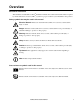
Overview Save these instructions This manual is an addendum to Larkin® installation manuals and contains technical information required by American Power Conversion (APC®) systems for proper condenser system installation and operation. Safety symbols that may be used in this manual Electrical Hazard: Indicates an electrical hazard, which, if not avoided, could result in injury or death.
Safety Note: All work should be performed by APC authorized personnel only. Follow all local and national codes when installing this system. Only a licensed plumber may connect the water lines. Warning: A licensed plumber is required to connect all plumbing in compliance with all local and national codes. Caution: Keep your hands, clothing, and jewelry away from moving parts. Check dry cooler fans for foreign objects before starting the unit. Heavy: This equipment is heavy.
Inspecting the Equipment Your equipment has been tested and inspected for quality assurance prior to shipment from APC. To ensure that the equipment has not been damaged during transit, carefully inspect both the exterior and interior of the equipment immediately upon receipt. Filing a claim If damage is identified upon receipt of the equipment, note the damage on the bill of lading and file a damage claim with the shipping company. Contact APC for information on filing a claim with the shipping company.
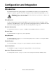
Configuration and Integration Introduction The included electrical data, piping diagram, system installation information, and operational control settings are required to properly connect and configure the Outdoor Heat Exchanger (OHE) to operate. Warning: Failure to follow this information may result in poor performance or damage to air conditioning products and/or the OHE.
Electrical Connections REMOTE AIR COOLED CONDENSER AFX AFX FM FM USER INTERFACE Remote Air Cooled Condenser 5
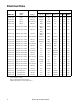
Electrical Data Ambient Temperature OHE SKU Larkin P/N Voltage 95° F (35° C) 105° F (40.5° C) ACCD75018 FCB-8 208-230/1/60 AFX018 N/A N/A 3.9 15.0 15.0 ACCD75019 FCB-8 460/1/60 AFX018 N/A N/A 2.4 15.0 15.0 ACCD75028 FCB-14 208-230/1/60 FM35 AFX018 N/A 7.8 15.0 15.0 ACCD75322 FCB-14 460/1/60 FM35 AFX018 NA 4.8 15.0 15.0 ACCD75301 LNH-S01-A007 12FPI 208-230/3/60 AFX018/ FM35 AFX018 N/A 4.8 15.0 25.
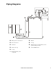
Piping Diagrams Head pressure control valve** Module Flooded receiver** “P” trap Condenser Pitch in direction of refrigerant flow, 1/2 in. per 10 ft (4 mm per meter).
System Installation Installing the flooded receiver Attach the flooded receiver to the side of the heat exchanger. 1. Position the mounting brackets on the desired side of the heat exchanger. Mount each bracket to the heat exchanger using two screws for each bracket, and using the top holes in each bracket for placement. Caution: Be careful to select a mounting location that will avoid hot gas inlet and liquid outlet lines in the condenser. 2.
Refrigerant Piping Recommended line sizes See the NetworkAIR FM Installation Manual for detailed installation information. Equivalent Length ft (meters) 50 (15.
Fittings and valves See the NetworkAIR FM Installation Manual for detailed installation information. ASHRAE refrigerant equivalent lengths for fittings and valve standards Type of Fitting or Valve - Equivalent Length of Pipe in Feet 10 Nominal Size of Pipe (in inches) Gate Valve Std Elbow 90° Reduced Coupling Side Outlet “T” Angle Valve 1/2 0.7 1.6 1.6 3.0 7.0 3/4 0.9 2.0 2.0 4.0 9.0 1 1.0 2.6 2.6 5.0 12.0 1 1/4 1.5 3.3 3.3 7.0 15.0 1 1/2 1.8 4.0 4.0 8.0 18.0 2 2.
Charging the system 35° C (95° F) Ambient Condenser Flooded Recievers APC SKU Larkin Model Charge needed for Larkin Condensers filled 100% in kg (lbs) System charge CRAC Unit Charge + Larkin condenser summer charge + Liquid line charge between CRAC unit and condenser + optional flooded receiver Optional Flooded Charge Receiver Dimensions Larkin Condenser Summer Charge in kg (lbs) Flooded Receiver Options in kg (lbs) Weight - kg (lbs) Diameter - mm (in) Length - mm (in) ACCD75018 & 019 FCB-8 12.
40.5° C (105° F) Ambient Condenser Flooded Receivers APC SKU Larkin Model Charge needed for Larkin Condensers filled 100% in kg (lbs) System charge CRAC Unit Charge + Larkin condenser summer charge + Liquid line charge between CRAC unit and condenser + optional flooded receiver Optional Flooded Charge Receiver Dimensions Larkin Condenser Summer Charge in kg (lbs) Flooded Receiver Options in kg (lbs) Weight - kg (lbs) Diameter - mm (in) Length - mm (in) ACCD75028 & 322 FCB-14 19.1 (42.0) 12.
Piping Volume Overall System Charge = CRAC Unit Charge* + Larkin Condenser Summer Charge + Liquid line charge between CRAC unit and Condenser + Optional Flooded Charge. Density of liquid R22 @ 105°F 260 psig = 70.3 lb/ft3 (40.5°C 1793 kPa = 95 N m) Inside diameter for 7/8 in (22 mm) OD ACR copper tube is 0.785 in (20 mm) Cross sectional area for 0.785 in (20 mm) ID pipe is 0.00336 ft2 (312 mm2) R22 in liquid line = area × Length in ft × density = 0.00336 ft2 × L ft × 70.
Setpoint adjustment Setpoint adjustment is defined as the temperature at which the relay de-energizes. Use the setpoint dial on the front of the controller to adjust the setpoint. Differential adjustment Differential adjustment is defined as the change in sensor temperature between energizing and deenergizing the relay. Use the potentiometer marked “DIFF” to adjust the temperature differential.
Adjusting the S350A/B Refer to the following steps for adjusting stage module settings. Electrical Hazard: Disconnect power supply to avoid possible electrical shock or equipment damage. More than one disconnect may be required to completely de-energize equipment. 1. Ensure all power to system is off. Each stage module may be receiving power from separate sources. Make sure all power sources to each stage module are off. 2. Remove the stage module cover by loosening the four captive cover screws. 3.
Default jumper settings for “heating”, relay NC Mode Fan Connection Sensor Reading Relay Fan Status Standard Operation Control Failure Heating NC to C Below Setpoint Energized OFF Above Setpoint De-energized ON Will drive head pressure toward setpoint. May drive head pressure below desired level. Heating NC to C S350** S350** OFFSET S2 OFFSET S3 (°F) (°F) Model LNH 1140 rpm Larkin Condensers Fan Config.
Example of operation using an FM50 and LNH-S03A026 condenser: The condenser has three fans. The first fan is located closest to the header, is controlled by a P66 electronic speed control, and is not discussed here. The second fan (stage 1) is controlled by an A350A temperature control module and the third fan (stage 2) is controlled by an S350A temperature stage module. Settings are as follows: • A350A and S350A differential is 3°. • A350A setpoint is 100°F ambient. • S350A offset is 10°.
Jumper setting: cooling with relay NO Mode Fan Connection Sensor Reading Relay Fan Status Standard Operation Control Failure Cooling NO to C Below Setpoint De-energized OFF Above Setpoint Energized ON Will drive head pressure toward setpoint. Unit will trip on high pressure switch. Cooling NO to C Example of operation using an FM50 and LNH-S03A026 condenser: The condenser has three fans.
Jumper set as “cooling”, relay NO Model FM35 FM40 FM50 AFX018 AFX065 S350** OFFSET S2 (°F) S350** OFFSET S3 (°F) Condenser Model Fan Config.
APC Worldwide Customer Support Customer support for this or any other APC product is available at no charge in any of the following ways: • Visit the APC Web site to access documents in the APC Knowledge Base and to submit customer support requests. – www.apc.com (Corporate Headquarters) Connect to localized APC Web sites for specific countries, each of which provides customer support information. – www.apc.com/support/ Global support searching APC Knowledge Base and using e-support.