AIS® 3000 and XR Battery Enclosure 10-40kVA 400V Operation Manual
AIS® 3000 and XR Battery Enclosure 10-40kVA 400V Operation Manual www.a pc.com www.a pc.com www.a pc.
Contents IMPORTANT SAFETY INSTRUCTIONS . . . . . . . . . . . . . . . . . . . . . 1 Warning/note symbols . . . . . . . . . . . . . . . . . . . . . . . . . . . . 1 Environmental symbols . . . . . . . . . . . . . . . . . . . . . . . . . . . 1 General safety . . . . . . . . . . . . . . . . . . . . . . . . . . . . . . . . . . 2 Introduction . . . . . . . . . . . . . . . . . . . . . . . . . . . . . . . . . . . . . . . 3 The AIS 3000 Family Range . . . . . . . . . . . . . . . . . . . . . . . . . . . .
Front Panel Removal/Installation . . . . . . . . . . . . . . . . . . . . . . . 18 Removal . . . . . . . . . . . . . . . . . . . . . . . . . . . . . . . . . . . . 18 Installation . . . . . . . . . . . . . . . . . . . . . . . . . . . . . . . . . . . 19 Air Filter Inspection/Replacement. . . . . . . . . . . . . . . . . . . . . . . 20 Air filter inspection . . . . . . . . . . . . . . . . . . . . . . . . . . . . . 20 Battery Replacement . . . . . . . . . . . . . . . . . . . . . . . . . . . . . . . .
Appendix ...............................................................40 UPS Components and Options. . . . . . . . . . . . . . . . . . . . . . . . . 40 352mm Enclosures . . . . . . . . . . . . . . . . . . . . . . . . . . . . . 40 523mm Enclosures . . . . . . . . . . . . . . . . . . . . . . . . . . . . . 40 System sizes, part Nos., number of Battery Modules and weights . . . . . . . . . . . . . . . . . . . . . . . . . . . . . . . . . . . . . 41 Part number coding: . . . . . . . . . . . . . . . . . . . . .
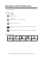
IMPORTANT SAFETY INSTRUCTIONS This guide contains important instructions that should be followed when handling the UPS, Battery Enclosures, and Batteries. Warning/note symbols WARNING! Risk of electric shock. CAUTION! Read this information to avoid equipment damage. Indicates important information. Note Indicates that more information is available on this subject in a different section of this manual. Indicates that more information is available on the same subject in a different manual.
IMPORTANT SAFETY INSTRUCTIONS General safety Two people to lift a component weighing between 18 - 32 kg. Indicates that a switch or current protection device is ON. Indicates that a switch or a breaker is OFF. For configurations including customer-supplied external batteries, refer to manufacturer’s battery installation and maintenance instructions.
Introduction Welcome to the Operation Manual covering the AIS® 3000 UPS and the Extended Run Battery Enclosure (XR Enclosure). This manual provides you with a detailed description of start-up, operation, and troubleshooting. Note The UPS manuals: Receiving and Unpacking - part # 990-1961 Site Planning and Electrical Installation - part # 990-2258 – are provided in the documentation storage area at the top right corner on the UPS (behind the Front Panel).
The AIS 3000 Family Range 352mm Enclosures ! Output Pwr Zone Probe 10/100Base-T Reset AP9619 10/100 Network Management Card EM Serial: Model: BATTERY UNIT Serial: Model: BATTERY UNIT Serial: Model: BATTERY UNIT Serial: Model: BATTERY UNIT Serial: Model: BATTERY UNIT Serial: Model: BATTERY UNIT Serial: Model: BATTERY UNIT Serial: Model: BATTERY UNIT www .apc.
The AIS 3000 Family Range WARNING! Only trained persons familiar with the construction and operation of the equipment, including the electrical and mechanical hazards involved, may install and remove system components. Details on the UPS sizes, runtime, weight etc. are available in the Appendix under UPS sizes, weights, and runtime configurations. Note Most illustrations show 523mm Enclosures but apply to both Enclosure sizes.
Start-Up (if applicable) Start-up is included with the UPS, and the start-up procedure described here is only applicable if the UPS requires a subsequent start-up. Note Power application WARNING! Only trained personnel familiar with the construction and the equipment may carry out the start-up procedure.
Start-Up (if applicable) After system boot-up, the display will atuomatically prompt you on how to confirm/select voltage and frequency as shown in the following. Voltage confirmation See display introduction under The Display. At the initial start-up, the display will prompt you through the following screens: Confirm Voltage Use 400V Yes, use 400V No, select another • When the Confirm Voltage prompt appears on the screen, use the arrow key on the display to select desired voltage, and press ENTER.
Operation Modes In a stand-alone installation, the UPS has four different operation modes. If the installation includes a Maintenance Bypass Panel test mode will also be available. Normal operation During normal operation, the UPS converts mains power to conditioned power for the connected load. Battery operation During battery operation, the UPS provides power to the connected load from its internal and (if applicable) external batteries for a finite period.
Operation Modes Maintenance bypass The UPS can be connected to an external Maintenance Bypass Panel. When activated, this panel bypasses the entire UPS Enclosure (only possible with an optional APC Maintenance Bypass Panel), feeding mains power directly to the load. An activated wrap-around Maintenance Bypass Panel completely isolates the UPS and allows all kinds of maintenance to be performed – including a replacement of the entire UPS.
The Display Introduction CAUTION! The display provides access to more functions than described in this manual. Those functions should not be accessed without the assistance of APC Customer Support in order to avoid unwanted load impacts. For APC World-wide Customer Support, refer to rear cover of this manual. Four Light Emitting Diode (LED) indicators report the operational status of the UPS.
Navigation Menu-driven user functions If you get beyond the functions described in the menu tree, do not proceed. Press ESC to go back.
Navigation Basic display navigation principles On the display, press ESC until you get to the Overview Screen, which provides you with basic system status information. Press UP, DOWN arrows to navigate the selector arrow and view all sub-menu screens. Chrg 100% Load 000% 230Vin 000Vout 50Hz Runtime: 0hr 0m Overview Screen Press ENTER to open the Main Menu screen. From here, you command, configure, and monitor the system.
Navigation Turn load ON. 1. From the Main Menu, select Control and press ENTER 2. Use UP/DOWN key to navigate to Turn Load ON, and press ENTER 3. Select YES, Turn Load ON Turn into bypass. 1. From the Main Menu, select Control and press ENTER 2. Use UP/DOWN key to navigate to UPS into bypass and press ENTER 3. Use UP/DOWN key to navigate to YES, UPS into bypass, and press ENTER Turn out of bypass. 1. From the Main Menu, select Control and press ENTER 2. Select UPS out of Bypass and press ENTER 3.
Navigation Load and batteries. Load: Percentage of the load in relation to the total UPS capacity. Bat Voltage: Shows either the positive or negative half of the battery voltage (the lower value of the two will appear). Bat Cap: Percentage charge on the batteries in relation to the total battery capacity. Runtime: The predicted runtime at the current load. Batteries. Bat AmpHr: Battery capacity, including both external and internal batteries. UPS Temp: The highest external battery temperature.
Navigation Logging From the logging screen on the Main Menu, you can view the 100 most recent UPS log events, and view the logged details of the events, such as date and time of occurrence, and event number. Control Status Setup Logging Display Diags Help Main Menu 1. From the Main Menu, select Logging 2. Select View Log 3.
Navigation Alarm threshold If the load level exceeds the preprogrammed threshold, the UPS will display a warning. Example: Alarm Thresholds Load: 20.0 kVA Runtime: 0 hr 0 min Alarm Threshold Screen To change the Alarm Thresholds, 1. Select Setup from the Main Menu 2. Select Alarms from the Setup Menu 3. Press ESC to return to the Main Menu Display setup From the Display Setup screen, you can select your display Language, Contrast and Beeper functions.
Navigation From the Beeper Setup Menu, select Beeper Setup. To change the beeper setup, select Beep at and press ENTER. You now have the following options: • Never: If you select this setting, the Beeper will be active at internal UPS errors only. • PwrFail+30: If you select this setting, the Beeper will be active at Internal UPS errors and at mains or bypass errors. The Beeper will only sound if the fault has been present for more than 30 seconds.
Front Panel Removal/Installation Removal Serial: Model: BATTER Y UNIT Serial: Model: BATTER Y UNIT Serial: Model: BATTER Y UNIT Serial: Model: BATTER Y UNIT Serial: Model: BATTER Y UNIT Serial: Model: BATTER Y UNIT Serial: Model: BATTER Y UNIT Serial: Model: BATTER Y UNIT www .apc.com www .apc.com To remove a Front Panel, use a coin or similar, and turn the 2 black lock devices away from the Display to horizontal level.
Front Panel Removal/Installation Installation Serial: Model: BATTER Y UNIT Serial: Model: BATTER Y UNIT Serial: Model: BATTER Y UNIT Serial: Model: BATTER Y UNIT Serial: Model: BATTER Y UNIT Serial: Model: BATTER Y UNIT Serial: Model: BATTER Y UNIT Serial: Model: BATTER Y UNIT www .apc.com www .apc.com To install a Front Panel, insert the two guide taps positioned at the bottom of the Front Panel into the two slots at the bottom of the Enclosure.
Air Filter Inspection/Replacement Air filter inspection The UPS and XR Enclosure Front Panels are fitted with air filters on the inside of the Front Panels for extra protection of systems installed in environments with conductive dust. Check the air filters once a month. If the air filters show visible dust or other impurities, the air filters must be replaced. Air filter part nos.
Air Filter Inspection/Replacement Serial: Model: BATTERY UNIT Serial: Model: BATTERY UNIT Serial: Model: BATTERY UNIT Serial: Model: BATTERY UNIT Serial: Model: BATTERY UNIT Serial: Model: BATTERY 12 pcs UNIT Serial: Model: BATTERY UNIT Serial: Model: BATTERY www.apc. com UNIT www.apc. com Remove the Front Panel from the Enclosure. For details on how to remove the Front Panel, see Front Panel installation/removal.
Air Filter Inspection/Replacement Position the new air filters in the Front Panel, ensuring that the metal side of the air filters face outwards. Remount the plate between the upper and lower air filters and reattach the 2 wing nuts. Reinstall the Front Panel.
Battery Replacement General safety prior to module replacement WARNING! • Only trained personnel familiar with the operation of the equipment, and the electrical and mechanical hazards involved, may install and remove system components. • The UPS and Battery Enclosure contain an internal energy source. Hazardous voltage may be present even when disconnected from the power source. Follow Total Power Off Procedure to completely de-energize the system.
Battery Replacement Removal of Battery Securing Brackets (if applicable) If your system is equipped with Battery Securing Brackets, follow the below procedure to remove the Brackets. Remove the M3 screw attaching the Battery Securing Bracket to the shelf. Push the Battery Securing Bracket to the left, push it upwards and remove.
Battery Replacement Battery Module removal Follow the below procedures if you need to change or add a Battery Module, e.g.
Battery Replacement UPS / XR Install the Battery Module in the lowest available bay (4 across in 523mm UPS versions, 2 across in 352mm UPS versions). Position the Battery Unit to slide in between the grooves and push completely into the UPS to ensure connection. If a problem is reported, ensure that the modules in question are correctly installed. If the problem persists, refer to the Troubleshooting section of this guide.
Network Management Card with Environmental Monitor The APC Network Management Card with Environmental Monitor (AP9619) is installed in the UPS as default. It is used for remote system control and monitoring, e-mail notifications etc. For configuration and use, refer to the separate user manual - Network Management Card with Environmental Monitor - shipped with the UPS.
How to Obtain Replacement Parts To obtain a replacement part, contact APC Customer Support (see rear cover). 1. In the event of a Battery Module failure, the display may show additional “fault list” screens. Press any key to scroll through these fault lists, record the information, and relay it to the APC representative. 2.
Total-Power-Off Procedure WARNING! Risk of electric shock - parts inside the UPS and XR Enclosure are energized from the battery supply even when the AC power is disconnected. Before electrical installation begins, follow the Total-Power-Off procedure to completely de-energize the system.
Total-Power-Off Procedure Refer to Seismic Anchoring in the Electrical Installation Manual for instructions on how to remove Seismic Battery Brackets (if applicable).
Display Messages/Troubleshooting This section lists the status and alarm messages that the UPS might display. The messages are listed in alphabetical order, and a suggested corrective action is listed with each alarm message to help you troubleshoot problems. Display messages Display message Meaning Corrective action Automatic Self Test Started. The UPS has started pre-programmed battery test. No corrective action necessary. Batt Temperature Exceeded Upper Limit.
Display Messages/Troubleshooting 32 Display message Meaning Corrective action Load Is No Longer Above Alarm Threshold. The load previously exceeded the alarm threshold and the situation has been corrected either because the load decreased or the threshold was increased. No corrective action necessary. Load Power Is Above Alarm Limit. The load has exceeded the userspecified load alarm threshold. Option 1: Use the display interface to raise the alarm threshold. Option 2: Reduce the load.
Display Messages/Troubleshooting Display message Meaning Corrective action System Failure Detected by Surveillance. The system has detected an internal error. Check for other alarms and contact APC customer support if problem persists. System Start Up Configuration Failed. System configuration error. Unable to determine system voltage and/or Enclosure size. Check for other alarms and contact APC customer support if problem persists. System Not Synchronized to Bypass.
Mechanical Bypass Mechanical Bypass Lever For increased availability, the UPS is equipped with an internal mechanical bypass system providing mains power directly to the output, bypassing all UPS electronics. CAUTION! The load is not protected by the UPS when the internal mechanical bypass system is active, and, the power is not conditioned. Turn into mechanical bypass If the UPS is running and controllable through the display, carry out steps 1 through 6. If not, go directly to step 4.
Mechanical Bypass ! Output Pwr Zone Probe 10/100Base-T Reset 10/100 AP9619 Network Management Card EM Turn the Mechanical Bypass Lever upwards to activate the internal mechanical bypass switch. Reinstall the Front Panel The load will now be supported directly by mains power. Turn into normal operation (from bypass operation) CAUTION! Never attempt to switch back the UPS into normal operation till you have verified that there are no internal UPS faults.
Maintenance Bypass Panel Operation procedure The Maintenance Bypass Panel (MBP) can be used to completely isolate the UPS in the event of an internal UPS fault. MBP (wall-mounted) To carry out this procedure, refer to the product-specific manual supplied with the Maintenance Bypass Panel.
LIMITED FACTORY WARRANTY The limited warranty provided by American Power Conversion Corporation (“APC”) in this Statement of Limited Factory Warranty applies only to Products you purchase for your commercial or industrial use in the ordinary course of your business.
LIMITED FACTORY WARRANTY Drawings, descriptions APC warrants for the Warranty Period and on the terms of the Warranty set forth herein that the APC Product will substantially conform to the descriptions contained in the APC Official Published Specifications or any of the drawings certified and agreed to by an authorized APC representative, if applicable thereto (“Specifications”).
LIMITED FACTORY WARRANTY IN NO EVENT SHALL APC, ITS OFFICERS, DIRECTORS, AFFILIATES OR EMPLOYEES BE LIABLE FOR ANY FORM OF INDIRECT, SPECIAL, CONSEQUENTIAL OR PUNITIVE DAMAGES ARISING OUT OF THE USE, SERVICE OR INSTALLATION OF THE PRODUCTS, WHETHER SUCH DAMAGES ARISE IN CONTRACT OR TORT, IRRESPECTIVE OF FAULT, NEGLIGENCE OR STRICT LIABILITY OR WHETHER APC HAS BEEN ADVISED IN ADVANCE OF THE POSSIBILITY OF SUCH DAMAGE.
Appendix UPS Components and Options 352mm Enclosures ! Output Pwr Zone Probe 10/100Base-T Reset AP9619 10/100 Network Management Card EM Serial: Model: BATTERY UNIT Serial: Model: BATTERY UNIT Serial: Model: BATTERY UNIT Serial: Model: BATTERY UNIT Serial: Model: BATTERY UNIT Serial: Model: BATTERY UNIT Serial: Model: BATTERY UNIT Serial: Model: BATTERY UNIT www .apc.
Appendix UPS Components and Options System sizes, part Nos., number of Battery Modules and weights Height (identical for all Enclosure sizes) 1490mm Depth (identical for all Enclosure sizes) 854mm Installed weight Installed weight System Size/ Enclosure width APC Part No. kg APC Part No. kg 10kVA 352mm ISVT10KH1B2S 308.7 ISVT10KH2B2S 404.7 10kVA 523mm ISVT10KH1B4S 345.4 ISVT10KH2B4S 441.4 10kVA 523mm ISVT10KH3B4S 537.4 ISVT10KH4B4S 633.4 15kVA 352mm ISVT15KH2B2S 404.
Appendix UPS Components and Options Battery Module One Battery Module consists of 4 Battery Units (shipping in the UPS Enclosure). Serial: Model: BATTE RY UNIT Serial: Model: BATTE RY UNIT Serial: Model: BATTE RY UNIT Serial: Model: BATTE RY UNIT 4 x 24kg Front Panel overview www .apc .com www .apc.
Appendix UPS Components and Options Stabilizing Bracket Always install the Stabilizing Brackets on the 352mm Enclosure (shipped with the UPS) to enhance the stability of the Enclosure.
Appendix UPS Components and Options User interface ! Output Pwr Zone Probe 10/100Base-T Reset 10/100 AP9619 Network Management Card EM Serial: Model: BATTERY UNIT Serial: Model: BATTERY UNIT Serial: Model: BATTERY UNIT Serial: Model: BATTERY UNIT Display: user-control interface used to configure the functionality, monitor the system, set alarm thresholds, and to provide audible and visual alarms.
Options Battery Securing Bracket and Floor Anchoring In seismic areas, each Battery Module must be secured with a Battery Securing Bracket.
Appendix Options Extended Run Battery Enclosure (XR Enclosure) and Battery Module XR Enclosure with Front Panel Battery Module 1490mm Serial: Model: BATTER Y UNIT Serial: Model: BATTER Y UNIT Serial: Model: BATTER Y UNIT Serial: Model: BATTER Y UNIT www .apc.
Appendix Options Part Numbers for XR Enclosures XR Enclosure Enclosure with DC breaker, DC fuses and 2 Battery Modules (expandable to 6) ISVTBXR2B6S Enclosure with DC breaker, DC fuses and 6 Battery Modules ISVTBXR6B6S Enclosure with DC fuses and 2 Battery Modules (expandable to 6) ISVTXR2B6S Enclosure with DC fuses and 6 Battery Modules ISVTXR6B6S Part Number for Battery Module Battery Module Battery Module SYBT4 AIS® 3000 & XR Battery Enclosure 10-40kVA, 400V, Operation Manual – 990-2259 47
Appendix Options Maintenance Bypass Panels with Power Distribution Capability Further details on APC Maintenance Bypass Panel (MBP) with Power Distribution Capability are available on www.apc.com. Note MBP (wall-mount) 949mm 750mm 190mm The Maintenance Bypass Panel provides overcurrent protection to the entire UPS system. It is also used to bypass the utility power around the UPS instead of through the system, e.g. when UPS maintenance is carried out.
APC Worldwide Customer Support Customer support for this or any other APC product is available at no charge in any of the following ways: • Visit the APC Web site to access documents in the APC Knowledge Base and to submit customer support requests. – www.apc.com (Corporate Headquarters) Connect to localized APC Web sites for specific countries, each of which provides customer support information. – www.apc.com/support/ Global support searching APC Knowledge Base and using e-support.