
User Manual


11Rack ATS AP44xx User Manual
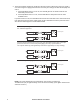
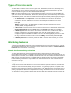
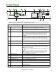
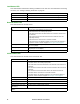
Front Panel
NOTE: Your Rack ATS is configured so the display back light turns off after 10 minutes of inactivity.
Press any display navigation button to illuminate the back light.
Item Function
Preference A/B Button Press to set a preferred source: the first press sets source A, the second
press sets source B, and the third press sets no preference.
Source A and B LEDs Indicate preferred source. If no source is preferred, both LEDs are
illuminated. You can also see preferred source on the LCD Display.
Input Connector LEDs Provide information about input voltage from each source. If the RMS
input voltage and measured frequency are within the selected tolerance
range, the corresponding indicator will be illuminated. In a normal
operating condition (full source redundancy) both sets of LEDs are
illuminated.
Output Connector LEDs Indicate which source is being used for the output (only one path will be
illuminated at any time). Together, the Source Preference LEDs, the
Connector LEDs, and the Output LED show the power flow through the
ATS.
Output LED Shows that voltage is available at the output of the ATS.
LCD Display View ATS status, settings, and product information. See “LCD Display
Screens” on page 13 for more information on LCD display screens.
Display navigation buttons On the LCD Display, icons indicate the purpose of adjacent buttons.
Home: Press to move through default screens or return to default
screens from menu screens.
Down: Press to move through default screens, menu items, or menu
screens.
Select: Press to navigate to the main menu from default screens,
select menu items, or return to the main menu from menu screens.
See “LCD Display Screens” on page 13 for more information.
Load Status LED See “Load Status LED” on page 12
Network Status LED See “Network Status LED” on page 12
10/100 Base-T Connector Connects the ATS to the network.
10/100 Status LED See “10/100 Status LED” on page 12.
USB port Use a USB drive to upgrade the firmware or download log files.
Serial port Connect your computer to the ATS for local access to the CLI. Use the
supplied Serial Communication cable (APC by Schneider Electric part
number 940-0144A).
Reset button Restarts ATS network and serial communication.
pdu0733b
- Warni ng
- OK
- Over load
Serial
10/100
USB
Netwo rk
x
Reset
Preference
A/B
B