User Manual Rack LCD Console AP5717, AP5717CH, AP5717F, AP5717G, AP5717J, AP5717R, AP5717UK, AP5719 990-3863-001 Publication Date: October, 2013
Schneider Electric IT Corporation Legal Disclaimer The information presented in this manual is not warranted by the Schneider Electric IT Corporation to be authoritative, error free, or complete. This publication is not meant to be a substitute for a detailed operational and site specific development plan.
Contents General Information................................................................... 1 Overview . . . . . . . . . . . . . . . . . . . . . . . . . . . . . . . . . . . . . . . . . . . . . . . . . . . .1 Important Safety Information . . . . . . . . . . . . . . . . . . . . . . . . . . . . . . . . . . .1 Related Documents . . . . . . . . . . . . . . . . . . . . . . . . . . . . . . . . . . . . . . . . . . .1 User Comments . . . . . . . . . . . . . . . . . . . . . . . . . . . . . . . . . . . . . . . . .
Operation ..................................................................................... 9 Basic Functions . . . . . . . . . . . . . . . . . . . . . . . . . . . . . . . . . . . . . . . . . . . . . .9 Opening the Rack LCD Console . . . . . . . . . . . . . . . . . . . . . . . . . . . . . . . 9 Closing the Rack LCD Console . . . . . . . . . . . . . . . . . . . . . . . . . . . . . . . . 9 Powering off and restarting . . . . . . . . . . . . . . . . . . . . . . . . . . . . . . . . . . . 9 Standby mode . .
General Information Overview The Rack LCD Console features a 17” or a 19” LCD panel, a full keyboard, and a touch pad in a rack-mountable sliding housing. The Rack LCD Console is intended for use with compatible target devices (a KVM switch or server). Important Safety Information Read the instructions carefully to become familiar with the device before trying to install, operate, service or maintain it.
Safety SAVE THESE INSTRUCTIONS! This manual contains important instructions that must be followed during installation, operation, and maintenance of the device. DANGER HAZARD OF ELECTRIC SHOCK, EXPLOSION, OR ARC FLASH • Consult your power company if you are unsure if your power source is compatible with the device requirements.. • The device is designed to use with IT power distribution systems with up to 230V phase-tophase voltage. • Do not overload the AC branch circuit that provides power to the rack.
Additional Safety Information Before you begin Verify that the system is free from all short circuits and grounds, except those grounds installed according to local regulations (according to the National Electrical Code in the U.S.A., for instance). If high-potential voltage testing is necessary, follow recommendations in equipment documentation to prevent accidental equipment damage. Before energizing equipment: • Remove tools, meters, and debris from equipment. • Close the equipment enclosure door.
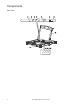
Components Front View EXIT MENU LCD POWER UPGRADE FW UPGRADE NUM LOCK 4 CAPS LOCK SCROLL LOCK RESET User Manual Rack LCD Console aem0351b Stand by
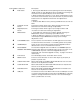
Item Number Component Description EXIT button 1. Pressing the EXIT button without opening the On Screen Display (OSD) initiates an auto adjustment which reconfigures all settings for the monitor to the optimum display values of the OSD. 2. While the OSD user interface is in use, press the EXIT button to exit the current menu and return to the previous menu or, press the EXIT button to leave an adjustment menu when the adjustment is complete. 3.
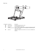
Rear View 1 PS/2 - USB CPU aem0351a 0 POWER Item Number Component Description Power Socket Standard 3-prong AC power socket. Power Switch Standard ON/OFF rocker switch Custom Port for connecting the Rack LCD Console to the target device (KVM Communication Port switch or server) using one of the included custom communication cables (PS2 or USB). USB Port USB pass-through from the USB Port on the front of the Rack LCD Console.
Installation Brackets Use only the hardware provided to install the Rack LCD Console in the rack. 1. Attach the left and right mounting rails to the inside of the rack. The flange that supports the Rack LCD Console station will be to the inside. a. Screw the front flanges to the rack first. na0347a 2. Slide the bars with the rear flanges toward the rack until the flanges make contact with the rack then screw the rear flanges to the rack. 3. Slide the Rack LCD Console () onto the support flanges ().
4. Slide the rear attachment sliding brackets along the slide bars until they contact the rear of the Rack LCD Console. Use the supplied M4 x 6 screws to attach the bars to the rear of the Rack LCD Console switch. Fully tighten these screws. 6. If the Rack LCD Console is moving properly in the brackets, fully tighten the screws inserted in step 3. aem0348a 5. Slide the Rack LCD Console open and closed two or three times to be sure it is operating smoothly.
Operation Basic Functions Opening the Rack LCD Console CAUTION HAZARDS RESULTING FROM MISUSE • Never lean on the device. • Slide rail mounted equipment is not to be used as a shelf or a work space. Do not set objects on the device. Failure to follow these instructions can result in injury or equipment damage. To access the console, slide the Rack LCD Console out of the rack and raise the cover. Closing the Rack LCD Console Close the cover and slide the Rack LCD Console into the rack.
LCD OSD (On Screen Display) configuration Button Function MENU 1. Starting: Pressing the MENU button initiates the LCD OSD and brings up the Main menu. 2. While the OSD user interface is in use, when a setting choice is reached, pressing the MENU button brings up the setting adjustment window. Right/Up Arrow Button Clicking the Right/Up Arrow button moves the cursor Right or Up through the menus, or increases the value when making an adjustment.
Firmware Upgrade Mode Check www.apc.com regularly to find the latest information and firmware upgrade packages. Note: Do not connect the RJ-11 port marked “Upgrade” to a public telecommunication network. Start the upgrade To download the firmware upgrade package: 1. Turn off the power to the Rack LCD Console. 2. Slide the Firmware switch to RECOVER. 3. Turn on the power to the Rack LCD Console.
Exit firmware upgrade mode 1. Slide the Firmware Upgrade Recovery Switch to the Normal position. 2. Remove the Firmware Upgrade cable from the Firmware Upgrade Port of the Rack LCD Console. 3. Turn the power to the Rack LCD Console OFF and then turn the power ON. Firmware upgrade recovery There are three conditions that call for firmware upgrade recovery: • If the firmware of the Rack LCD Console becomes corrupted and is unable to operate. • When a firmware upgrade is interrupted.
Troubleshooting Symptom Action There are ghost images on the external monitor The distance between the external console and the Rack LCD is too great. The maximum VGA cable distance should not exceed 20m and in some cases may need to be shorter. Replace the VGA cable with one of an appropriately short length. Some characters entered from the keyboard The keyboard layout setting for the port does not match the do not display correctly. keyboard you are using.
Specifications Function Server Connections Connectors Communication ports External mouse Firmware upgrade port Power USB 1.1 hub USB 1.
Worldwide Customer Support Customer support is available at no charge via e-mail or telephone. Contact information is available at www.apc.com/support/contact. © Schneider Electric, APC and the APC logo are owned by Schneider Electric Industries S.A.S., or its affiliated companies. All other trademarks are property of their respective owners.