MasterSwitch Power Distribution Unit AP9211 AP9212 AP9217 AP9218 Users Guide
MasterSwitch Power Distribution Unit Contents Introduction . . . . . . . . . . . . . . . . . . . . . . . . . . . . . . . . . 1 Product Description . . . . . . . . . . . . . . . . . . . . . . . . . . . . . 1 Front panel—1 LEDs—2 Rear panel—3 Initial Setup . . . . . . . . . . . . . . . . . . . . . . . . . . . . . . . . . . . 4 Configuring TCP/IP settings—4 Customizing your configuration—4 Auto-configuration—4 Managing the MasterSwitch PDU. . . . . . . . . . . . . . . . . . 5 Management Interfaces . . . . . .
Contents Help . . . . . . . . . . . . . . . . . . . . . . . . . . . . . . . . . . . . . . . . 24 Accessing and Navigating the Online Help—24 APC Interactive Assistant—24 About Card—24 Configuring and Using E-mail Notification . . . . . . . . . . 25 Configuring E-mail Recipients . . . . . . . . . . . . . . . . . . . . 25 Settings—25 Configuring the local SMTP server—25 Testing E-mail—25 Configuring SMTP and DNS Settings . . . . . . . . . . . . . . . .
Contents Product Information . . . . . . . . . . . . . . . . . . . . . . . . . . 43 Warranty Information . . . . . . . . . . . . . . . . . . . . . . . . . . 43 Obtaining service—43 Warranty exclusions—43 Obtaining Customer Support . . . . . . . . . . . . . . . . . . . . . 44 Life-Support Policy . . . . . . . . . . . . . . . . . . . . . . . . . . . . . 45 General policy—45 Examples of life-support devices—45 Specifications . . . . . . . . . . . . . . . . . . . . . . . . . . . . . . . . .
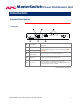
MasterSwitch Power Distribution Unit Introduction Product Description Front panel . Re-initializes the MasterSwitch PDU without affecting the outlet state. ! Reset Button " Status LED # Link-RX/TX LED Indicates the status of the Ethernet LAN connection and the state of the management card, as described in LEDs on page 2. $ Eight Outlet Power LEDs Indicates whether the associated outlet is on.
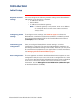
Introduction Product Description continued LEDs Each outlet has a corresponding LED that indicates the state of the outlet, and two LEDs indicate the status of the entire unit. The following table describes the conditions indicated by the LEDs. LED Status Description On The Outlet is on. Off The Outlet is off. Off The MasterSwitch PDU has no power. Green The MasterSwitch PDU has valid network settings. Flashing Green The MasterSwitch PDU does not have valid network settings.
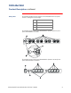
Introduction Product Description continued Rear panel The following table lists the features of the MasterSwitch rear panel shown in the figures on this page. ! Power Cord/ IEC Inlet " Outlets # Outlet Label $ Circuit Breaker The following figure shows the MasterSwitch (AP9211/AP9217) rear panel with NEMA 5-15 outlets. The following figure shows the MasterSwitch (AP9212/ AP9218) rear panel with IEC-320 C13 outlets.
Introduction Initial Setup Required network settings You must configure the following network settings of the MasterSwitch PDU before it can operate on a network: • IP address of the unit • Subnet Mask • IP address of the default gateway Note: If a default gateway is not present, enter an IP address of a computer that is on the same subnet and that is always active.
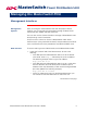
MasterSwitch Power Distribution Unit Managing the MasterSwitch PDU Management Interfaces Management Options After you configure a MasterSwitch PDU with the proper network settings, you can manage the unit remotely through its Web, Telnet Control Console, SNMP, and WAP interfaces. You can also use the Control Console to manage a MasterSwitch PDU locally through a serial connection. Only one user at a time can access a MasterSwitch PDU.
Managing the MasterSwitch PDU Management Interfaces continued Web interface, continued 2. Respond to the user name and password prompts. The default for both the Administrator user name and the Administrator password is apc (lowercase). After you log on, you can change the user name, password, and time-out values through the System menu. See User Manager on page 18.
Managing the MasterSwitch PDU Management Interfaces continued Control Console interface, continued Serial Interface. To access the unit’s Control Console, use the supplied null-modem cable to connect the serial port of the computer to the serial port on the MasterSwitch PDU, and set the terminal port to the following communication settings: Baud Rate 2400 Data Bits 8 Stop Bits 1 Parity None Handshaking None Local Echo Off Terminal Type ANSI (VT100) Logging on.
Managing the MasterSwitch PDU Management Interfaces continued WAP Interface To access and log on to the WAP (Wireless Application Protocol) interface of the MasterSwitch PDU: 1. In the URL Location field of the Micro browser: Enter the unit’s IP address followed by wap.wml. The following example shows a typical address: 123.456.78.9/wap.wml 2. Respond to the user name and password prompts.
Managing the MasterSwitch PDU Password-Protected Accounts Account access There are up to 16 Outlet User accounts, one Administrator account, and one Device Manager account. Each type of account provides a different level of access to the management menus. • • • Each Outlet User account has access only to the outlets assigned to it. The Administrator and Device Manager accounts have access to all outlets. The Administrator account can configure and manage all other accounts.
MasterSwitch Power Distribution Unit Menu Items Introduction Management Options Both the Web and Control Console interfaces provide the capabilities that this section describes for managing the MasterSwitch PDU, but the information in this section is based on the Web interface. If you are using Telnet or a serial interface to access the MasterSwitch PDU, terminology may differ from what is used here. Menu access depends on which type of account has logged on.
Menu Items Outlets Outlet Control Actions You can perform the following Outlet Control Actions on individual outlets or on all accessible outlets as a group (by Master Outlet Control). You can apply a Control Action only to an outlet that is not executing a command. Item Definition Immediate On The outlet turns on. Immediate Off The outlet turns off. Immediate Reboot The outlet turns off immediately, waits the outlet’s Reboot Duration time, and turns on.
Menu Items MasterSwitch Configure Device Settings Item Unit Name Outlet Configuration Definition The name of the MasterSwitch PDU. Maximum: 23 characters. Coldstart Delay The time that the MasterSwitch PDU waits before applying power to outlets after AC power is applied to the unit. Reboot Duration The longest reboot duration of any outlet in the group of accessible outlets. You can change this value only by modifying the Reboot Duration of individual accessible outlets.
Menu Items Event Log Displaying the Event Log To display the Event Log, select the Event Log menu in the Web interface or press CTRL + L in the Control Console interface. The Event Log displays the following information for the most recent 300 events for the MasterSwitch PDU. Retrieving the Event Log by using FTP Item Description Date The date on which the event occurred (DD/MM/YYYY) Time The time at which the event occurred (HH:MM:SS) Event Description of the event.
Menu Items Event Log continued Retrieving the Event Log by using FTP, continued 3. Type get event.txt. The MasterSwitch PDU transmits the Event Log, containing at least the last 300 events, to your specified drive. The screen displays information similar to the following. ftp>get event.txt 200 Command okay. 150 Opening data connection for event.txt 226 Closing data connection. ftp: 3694 bytes received in 0.11Seconds 33.58Kbytes/sec. ftp> Using a spreadsheet to view the Event Log To view the event.
Menu Items Network TCP/IP The TCP/IP section of the Network menu displays settings for the MasterSwitch PDU and allows you to configure the following TCP/IP settings. Item System IP Subnet Mask Default Gateway BOOTP TFTP/FTP Description The IP address of the MasterSwitch PDU The network subnet mask The local default gateway (router address) Enables or disables BOOTP requests for TCP/IP settings at startup.
Menu Items Network continued Telnet/Web T. Port Menu Item Definition Access Enables or Disables Telnet access. Port The TCP/IP port where the Telnet server for the MasterSwitch PDU resides. Telnet Default: port 23 Access Enables or Disables Web access. Port The TCP/IP port where the Web server for the MasterSwitch PDU resides.
Menu Items Network continued SNMP, continued Access control. The Access Control section of the SNMP menu identifies the current settings for all four SNMP channels and provides the configurable values for a selected channel. Item Community Name Definition The password that the NMS (identified by the NMS IP option) must use for SNMP access to the MasterSwitch PDU. The allowed access type is defined by the Access Type option. Maximum: 15 characters. Limits access to the NMS or NMSs specified.
Menu Items System User Manager The User Manager section of the System menu displays the following configurable properties of the Administrator and Device Manager accounts. Administrator Account Item Auto Logout Definition The amount of time the user can be inactive on the system before being logged out automatically. Default: 3 minutes. One of the following settings: Authentication • Basic: Causes the Web Interface to use standard HTTP 1.1 login (base64-encoded passwords).
Menu Items System continued User Manager, continued Device Manager Account Item Definition The user name. User Name Maximum: 10 characters Default: device The password for HTTP 1.1 authentication only. Password Maximum: 10 characters Default: apc The password for MD5 only.
Menu Items System continued Outlet User Management You can create up to 16 independent Outlet User accounts for a MasterSwitch PDU. Current Outlet User List. The list shows the existing outlet user accounts and the outlets to which they have access. To select an existing account to edit or delete, click on the underlined user name, To add a user, select Add New User. Configure the Outlet User Account Settings. Following are the configurable settings for Outlet User Manager. .
Menu Items System continued Identification Item Date/Time Definition Name The system name used to identify the device. Name will be used for the sysName OID in the SNMP agent. Contact The contact for or owner of the device. Contact will be used for the sysContact OID in the SNMP agent. Location The physical location of the device. Location will be used for the sysLocation OID in the SNMP agent. . Item Definition Date The date for the system in the following format: MM/DD/YY.
Menu Items System continued File Transfer The File Transfer section of the System menu provides access for managing file transfers. Item Description Remote TFTP Server IP The IP address of the remote TFTP server defined in the Network menu’s TFTP/FTP settings. TFTP: Remote Server IP Remote FTP Server IP The IP address of the remote FTP server defined in the Network menu’s TFTP/FTP settings.
Menu Items System continued Tools Item Links Definition No Action Causes no action. Reboot Card Restarts the operation of the Management Card, but does not affect the state of the MasterSwitch outlets. Reset Card to Defaults Restores all configuration settings, including TCP/IP settings and user accounts, to their defaults and enables BOOTP. Reset Card to Defaults Except TCP/IP Restores all configuration settings to the default except TCP/IP settings.
Menu Items Help Contents The Contents screen provides an overview of many parameters reported and configured through the Web and Control Console interfaces. Accessing and Navigating the Online Help To access the online help, do one of the following: • In the Web interface, select Help at the lower left in the navigation frame. • In the Control Console, type ? to access the Help menu.
MasterSwitch Power Distribution Unit Configuring and Using E-mail Notification Configuring E-mail Recipients Menu options To identify up to four e-mail recipients, use one of the following: • • The Recipients option of the Web interface’s Events menu The E-mail option of the Control Console’s Network Menu Settings Setting To Address Description Defines the user and domain names of the recipient.
Configuring and Using E-mail Notification Configuring SMTP and DNS Settings Requirements for using SMTP To use the Simple Mail Transfer Protocol (SMTP) to send e-mail when an event occurs, you must define the following settings: • • • The IP address of the Domain Name Service (DNS) server. The DNS name of the SMTP server and the From Address settings for SMTP. The e-mail addresses for a maximum of four recipients.
MasterSwitch Power Distribution Unit Event-Related Menus and Options Event Log Logged events The Management Card’s event log records normal and abnormal Management Card (system) events and MasterSwitch events. Any conditions that cause an SNMP trap, except for SNMP authentication failures, are logged as events. For a list of all events, see Management Card and MasterSwitch Events on page 36.
Event-Related Menus and Options Event Log continued Accessing the log, continued FTP. The event.txt file is a text version of the Management Card’s event log. • • • It is tab-delimited so that it can be imported into any spreadsheet application. It reports as many as 5000 events that occurred since the log was last deleted. It includes information that is not displayed in the Management Card’s event log as displayed by the Web interface and control console. – The version of the event.
Event-Related Menus and Options Actions Option (Web Interface only) Enabling and disabling event actions Use the Actions option of the Events menu to enable or disable the following for events that have a specified severity level: • • • Events Log SNMP Traps Email Some Management Card (system) events do not have a severity level, and you cannot disable actions for those events.
Event-Related Menus and Options Recipients Option Trap receivers You can define up to four NMSs to be used as trap receivers when an event occurs that has SNMP traps enabled. In the Web interface, use the Trap Receiver settings, available through the Recipients option of the Events menu. In the control console, use the SNMP option of the Network menu. Item Definition Community Name The password (15 characters or less) used when traps are sent to the NMS identified by the Receiver NMS IP setting.
Event-Related Menus and Options Recipients Option continued Email Recipients To identify up to four e-mail recipients to be notified of events, use one of the following: • • The Recipients option of the Web interface’s Events menu The Email option of the control console’s Network Menu Setting To Address Description Defines the user and domain names of the recipient. To use e-mail for paging, use the e-mail address for the recipient’s pager gateway account (for example, myacct100@skytel.com).
Event-Related Menus and Options Email Option Requirements for using SMTP To use the Simple Mail Transfer Protocol (SMTP) to send e-mail when an event occurs, you must define the following settings: • • • The IP address of the domain name service (DNS) server. The DNS name of the SMTP server and the From Address settings for SMTP. The e-mail addresses for a maximum of four recipients.
Event-Related Menus and Options How to Configure Individual Events Options to configure individual events You can configure individual events as follows: • • Use the evntlist.htm page. See Event list access on this page. Use the I2C Configuration Utility on the MasterSwitch CD. You edit a text file (.ini file,) convert that file to a binary configuration file (.cfg file), and use the Management Card Wizard to send the .cfg file to multiple Management Cards over the network.
Event-Related Menus and Options How to Configure Individual Events continued Event mask settings From the evntlist.htm page, to reconfigure actions for an event: 1. Click the link (the current hexadecimal code) for the event. 2. Enter a new hexadecimal code as an event mask to reconfigure the bits that control the actions for the event 3. Click Apply. The bits are numbered 0 to 23, from left to right. Note: Bit 5 and bits 14 through 23 are unused. Make sure these bits are always set to 0.
Event-Related Menus and Options How to Configure Individual Events continued Event mask example You enter the hexadecimal code 3B0800 as an event mask. The event mask configures the following bit settings: 0011 1011 0000 1000 0000 0000 The event is configured as follows: • • • • The severity level is severe. The event will be logged. Traps generated by the event will be sent to trap receivers 1 and 2. When the event occurs, e-mail will be sent to recipient 3 only.
Event-Related Menus and Options Management Card and MasterSwitch Events Event generation The Management Card and MasterSwitch both generate events, which are logged in the event log. Any event of either type generates a unique code, which you can use in applications to identify the event. To use SNMP traps for event notifications, you must first identify the trap receivers (up to four) by their specific IP addresses. See Trap receivers on page 30.
Event-Related Menus and Options Management Card and MasterSwitch Events continued Management card events Code Severity Description 0x0001 Severe System: Coldstart. (The Management Card was turned on.) 0x0002 Severe System: Warmstart. (The Management Card was reset after it was already turned on.) 0x0003 Warning System: SNMP configuration change. 0x0004 Informational System: An unauthorized user attempted to access the SNMP interface.
Event-Related Menus and Options Management Card and MasterSwitch Events continued MasterSwitch events Code Severity Description 0x0501 Warning An outlet has rebooted. If the outlet number is 0, then all outlets have rebooted. 0x0509 Warning An outlet has turned on. If the outlet number is 0, then all outlets have turned on. 0x050B Warning An outlet has turned off. If the outlet number is 0, then all outlets have turned off. 0x0510 Warning An outlet has changed configuration.
MasterSwitch Power Distribution Unit Security Security Features Planning and implementing security features As a network device that passes information across the network, the MasterSwitch PDU is subject to the same exposure as other devices on the network. Use the information in this section to plan and implement the security features appropriate for your environment.
Security Authentication Authentication versus encryption The MasterSwitch PDU controls access by providing basic authentication through user names, passwords, and IP addresses, but provides no type of encryption. These basic security features are sufficient for most environments, in which sensitive data is not being transferred.
Security Authentication continued MD5 authentication (Web interface), continued If you use MD5 authentication, which is available only for the Web interface, disable the less secure interfaces, including Telnet, FTP, and SNMP. For SNMP, you can disable write-only access so that read access and trap facilities are still available.
Security Authentication continued Summary of access methods Interface Serial Control Console Security Access Access is by user name and password. Notes Always enabled.
MasterSwitch Power Distribution Unit Product Information Warranty Information Limited warranty American Power Conversion (APC) warrants the MasterSwitch PDU to be free from defects in materials and workmanship for a period of two years from the date of purchase. Its obligation under this warranty is limited to repairing or replacing, at its own sole option, any such defective products.
Product Information Obtaining Customer Support Contacting Customer Support To obtain customer support for problems with the MasterSwitch PDU: 1. Contact Customer Support at a phone number or address listed under APC Worldwide Customer Support on page 53, and be ready to provide the serial number and date of purchase of the MasterSwitch PDU. 2. Be prepared to provide a description of the problem so that the technician can attempt to solve the problem over the phone. 3.
Product Information Life-Support Policy General policy American Power Conversion (APC) does not recommend the use of any of its products in the following situations: • • In life-support applications where failure or malfunction of the APC product can be reasonably expected to cause failure of the life-support device or to affect significantly its safety or effectiveness. In direct patient care.
Product Information Specifications Product specifications for AP9211 Type of Specification Electrical Physical Environmental Approvals Item Input: Nominal input voltage Acceptable input voltage Nominal input frequency Overcurrent protection Input connector Specification 100–120 VAC 90– 140 VAC 50/60 Hz 15-A circuit breaker 15 ft (4.5 m) attached NEMA 5-15 line cord Output: Output connectors Eight NEMA 5-15 outlets Maximum total current draw: 12 A Size (H × W × D) 1.75 × 17.0 × 6.5 in (4.4× 43.
Product Information Specifications continued Product specifications for AP9212 Type of Specification Electrical Physical Environmental Approvals Item Input: Nominal input voltage Acceptable input voltage Nominal input frequency Overcurrent protection Input connector Specification 100-230 VAC 90-250 VAC 50/60 Hz 12-A circuit breaker IEC-320 C14 inlet and IEC-320 C13-to-C14 power extender cord (2m) Output: Output connectors Eight IEC-320 C13 outlets Maximum total current draw: 10 A Size (H × W × D
Product Information Specifications continued Product specifications for AP9217 Type of Specification Electrical Item Input: Nominal input voltage Acceptable input voltage Nominal input frequency Overcurrent protection Input connector Specification 100–120 VAC 90– 140 VAC 50/60 Hz 20-A circuit breaker 12 ft (3.7 m) attached, NEMA L5-20, twist lock cord Physical Environmental Approvals Output: Output connectors Eight NEMA 5-15 outlets Maximum total current draw: 16A Size (H × W × D) 1.75 × 17.
Product Information Specifications continued Product specifications for AP9218 Type of Specification Electrical Physical Environmental Approvals Item Input: Nominal input voltage Acceptable input voltage Nominal input frequency Overcurrent protection Input connector Specification 100-230 VAC 90-250 VAC 50/60 Hz 20-A circuit breaker IEC-320 C20 inlet and IEC-320 8.2 ft (2.
MasterSwitch Power Distribution Unit Index A About Card, 24 Access limiting NMS access by IP address, 17, 42 Account types access to menus for each type, 9 Administrator, 18 Device Manager, 19 Outlet User, 20 menu, 21 DC Power Plant events listed and described, 38 Delete Log button, 27 Deleting the Event Log, 14 Description column, in event list, 33 Device Manager account, 19 Disabling e-mail for an event, 34 e-mail to a recipient, 31 email to a recipient, 25 sending any traps to an NMS, 30 sending authe
Index F Menus File Transfer, 22 From Address setting, for email, 32 From Address setting, for email, 26 Front panel, 1 FTP to retrieve text version of event log, 28 Event Log, 13 Help, 24 MasterSwitch, 12 Network, 15 Outlets, 11 System, 18 N Network menu, 15 Network menu options DNS (Control Console), 26 DNS (control console), 32 Email (Control Console), 25 Email (control console), 31 TCP/IP & DNS (Web interface), 26, 32 H Help Help menu, 24 Interactive Assistant, 24 I O I2C utility, to configure mu
Index Traps disabling for an event, 34 enabling for an event, 34 Troubleshooting e-mail configuration, 32 email configuration, 26 U W URLs URL for event list, 33 User Manager, 18 MasterSwitch Power Distribution Unit User’s Guide Warning severity level, 36 Warranty information, 43 Web interface, 5 Web port, configuring, 16 52
Contact Information APC Worldwide Customer Support Customer support for this or any other APC product is available at no charge. You can contact APC Customer Support in any of the following ways: • Use an APC web page to find answers to frequently asked questions (FAQs), to access documents in the APC Knowledge Base, and to submit customer support requests. – http://www.apcc.