KVM Switch AP9254 AP9258 For use in Europe: English, French, Italian, German, Portuguese, Spanish
Thank You! Thank you for selecting the APC KVM Switch. The APC KVM Switch has been designed for many years of reliable, maintenance free service. APC is dedicated to the development of high-performance electrical power conversion and control products and we hope that you will find this product a valuable, convenient addition to your computing system. Please read this manual! It provides important safety, installation and operating instructions that will help you get the most from your switch.
Table of Contents Chapter 1 - Product Overview Feature Overview .......................................................................................................... 1 Compatibility .................................................................................................................... 3 Chapter 2 - Installation Basic Installation ............................................................................................................. 4 Rack Mount Installation .........................
INSTRUCTIONS: The exclamation mark within an equilateral triangle is intended to alert the user to the presence of important operating and maintenance (servicing) instructions in the literature accompanying the appliance.
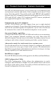
1.1 Product Overview - Feature Overview The APC KVM Switch allows you to control up to 64 computers with one keyboard, monitor and mouse. Each computer can be up to 25 feet away from the switch. The switch works with IBM PC/AT and PS/2 systems, and 100% compatible machines with support for VGA, SVGA, XGA and XGA-II video. PS/2 keyboard and PS/2 mouse peripherals are supported through the rear of the unit.
Push-button and keyboard switching In addition to using the on-screen menus, you can switch computer channels in one of three easy ways: via the APC KVM Switch channel push-buttons, with the Scan button or with a simple keyboard sequence. “Keep Alive” feature APC KVM Switch’s “Keep Alive” feature allows attached servers to power the unit in the event of a switch power failure. This prevents attached computers from locking up and keeps you from losing time and data.
1.2 Compatibility The APC KVM Switch requires a PS/2 mouse and keyboard. The following mice are known to be compatible: IBM PS/2-style Kensington Logitech Mouseman (PS/2) Logitech Trackman Microsoft Serial-PS/2 mouse Microsoft IntelliMouse Other manufacturers' mice may operate with the APC KVM Switch. If you experience problems using an untested mouse, contact APC Technical Support with the manufacturer and model number of the mouse in question.
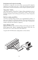
2.1 Installation - Basic Installation 1. Power down all computers that will be part of your APC KVM Switch system. Connecting your Peripherals 2. Locate your PS/2 keyboard, VGA video monitor and PS/2 mouse. 3. Plug your VGA monitor cable into the port on the back of your APC KVM Switch. Plug your PS/2 keyboard cable and your PS/2 mouse cable into the ports labeled and respectively.
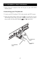
Connecting Computers to the APC KVM Switch 4. Locate your first input cable. It will have a 25-pin “D” connector at one end. Plug this cable into any numbered channel port on the rear of the switch. The other end of the input cable will have three connectors: a 15-pin “HDD” connector for your video, a PS/2 keyboard connection and a PS/2 mouse connection. The PS/2 connectors are designated by a mouse or keyboard icon on the connector. Plug these connectors into the matching ports on your computer.
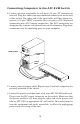
1 ! 0 z 0H /6 A, 50 , .1 0V 24 00 1 7. Power-up your APC KVM Switch unit first, then all attached servers. The APC KVM Switch and all attached servers should be powered-down before servicing the unit. Always disconnect the power cord from the electrical socket. 2.2 Rack Mount Installation 1. Remove the side screws that secure the cover on your KVM Switch. 2. Line up the holes in the side brackets with the screw holes in the side of the KVM Switch unit. 3.
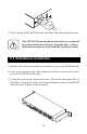
2.3 Advanced Installation Attaching Multiple APC KVM Switch Units 1. Follow steps 1-6 of the Basic Installation section. 2. Plug the 25-pin “D” connector of your input cable into any available channel port on the rear of your base switch unit. MADE IN USA 3. Plug the 15-pin video connector on the other end of the cable into on your first cascading KVM switch unit. Plug the port labeled the PS/2 mouse connector, designated by a mouse icon, into the port.
3.1 Basic Operations - Overview Your APC KVM Switch may be operated in a non-secure (no password required) or secure (password required) mode. All units ship defaulted to the non-secure mode. For information on implementing password security see the “Administrator Functions” section of Chapter 4. Computers may be powered-up one-at-a-time or all at once. No operator intervention is required during booting.
3.2 Keyboard Control The following notational conventions appear throughout this chapter to illustrate commands for operating the APC KVM Switch. Whenever you see one of the symbols listed on the left side of the table, substitute the corresponding steps or values listed on the right side of the table. Convention Key Sequence or Value Enter Command Mode: 1. Press and hold down the ‘Num Lock’ key. 2. Press and release the minus (-) key on the numeric keypad. 3. Release the ‘Num Lock’ key.
3.3 Keyboard Switching One of the ways to change the active channel in a non-secured APC KVM Switch system is by entering a short sequence of keystrokes on the keyboard. This is called keyboard, or hot-key, switching. Note: Hot-key switching is only available in the default non-secure state. For more information on secure versus non-secure operation, see the ‘Administrator Functions’ section of Chapter 4. The first set of keystrokes places your system in Command Mode.
3.4 System Control and Maintenance The following commands are used for system control and maintenance. Enter the command sequences to perform the actions described in the table below. Key Sequence Action Kn Sets the keyboard scan set where n is a scan set number 1-3. MR If you hot-plug your mouse cable, you may experience a loss of mouse signal. Use this command to restore the signal if you are using a computer with a standard PS/2 mouse driver.
4.1 OSD Operations - Activating OSD Activate on-screen display (OSD) by pressing either of the keyboard Control keys twice within one second. In non-secure mode, this brings up the main OSD Window, “Administrator Channel List”. In secure mode, activating OSD will bring up the “User Login” window. Type in your user name and press Enter. The system administrator should login as “Admin”, “Root” or “Administrator”. If the user name is valid, the password window will appear. Type your password and press Enter.
4.2 The OSD Window This window lists all named channels in your APC KVM Switch system. They will be listed alphabetically with their channel addresses and access status beside them. When in secure mode, only the channels that are accessible to the logged-in user will be listed. (See the section “Administrator Functions” for more information.
4.3 The Command Menu Once you have activated the main OSD Window, you can open the Command Menu by either pressing the Control key twice or by typing ALT-M. The Command Menu options are selected in the same manner as channels in the OSD Window. Scroll the Highlight Bar up and down and press Enter when your selection is highlighted.
4.4 Basic Channel Maintenance The Channel Maintenance Menu is accessed from the Administrator Command Menu, and is available if you are operating in non-secure mode or if you are the system administrator. Here you can add, delete or alter individual channels.
3. When prompted for another cascade level, type Y and press Enter. 4. Enter the number that corresponds to the computer port on the cascaded APC KVM Switch you are adding and press Enter. 5. When you have finished adding levels (up to two total), type N when prompted for another cascade level and press Enter. Press Esc anytime to exit this operation without adding the channel. Deleting an Existing Channel 1. Highlight the channel you wish to delete in the main OSD Window. 2.
4.5 The ID Window The ID Window appears when you change channels and displays the name of the selected channel. This window can be individually configured for each channel in your system. The characteristics of the ID Window can be changed from the Channel Maintenance Menu. This option is only available if you are operating in non-secure mode or if you are the system administrator. Changing the Size, Colour and Position of the ID Window 1.
Setting the ID Window Dwell Time This menu selection lets you set the time that the ID Window remains on screen after a channel switch. Each channel can be configured independently. The default time is set for 5 seconds. 1. From the main OSD Window, press the Control key twice or type Alt-M to access the Command Menu. 2. Select ‘‘Channel maintenance’’ from the Command Menu. 3. Choose the option ‘‘Dwell time for ID window’’. 4. Enter a number between 0-255 seconds. Entering 0 disables the ID Window.
4.6 Administrator Functions The Administrator Functions Menu is accessed from the Command Menu. Here, you can create an administrator password, set a system logout time and create individual user logins with specific access and privileges. This menu is only used if you are running your system in secure mode. If you configure an administrator password from this menu, your system will then be in secure mode. A lock symbol will appear to the right of the menu headings to indicate secure operation.
Push-Button and Hot-Key Channel Selection While in secure mode, all front panel push-buttons and hot-key channel selection methods are disabled. All other hot-key commands remain operational to the administrator only. In non-secure mode, all pushbuttons and hot-key commands function normally. Creating the Administrator Password 1. Press the Control key twice or type Alt-M for the Command Menu. 2. Select ‘‘Administrator Functions’’ from the Command Menu. 3.
Setting up additional users 1. Press the Control key twice or type Alt-M for the Command Menu. 2. Select ‘‘Administrator Functions’’ from the Command Menu. 3. Select ‘‘Setup User 1’’ from the Administrator Menu. 4. Choose the ‘‘Name’’ sub-menu and enter the name for this user. 5. Choose the ‘‘Password’’ sub-menu and enter the password and confirm it for this user. (Passwords are not case sensitive.) 6. Choose the ‘‘Access’’ sub-menu. Here, you will see a listing of all attached servers in the channel list.
5.1 Channel Scanning - Choosing a scan method APC KVM Switch's scanning feature allows you to automatically monitor, or scan, your computer channels without intervention. When keyboard activity is detected, scanning is suspended until all keyboard activity stops. Scanning then resumes with the next channel in sequence. Mouse activity will not affect scanning in any way. The length of time each channel remains on the screen, or dwell time, is configurable and can be changed at any time.
5.2 Setting the Scanning Order 1. From the main OSD Window, press the Control key twice or type Alt-M to access the Command Menu. 2. Choose ‘‘Scanning order’’ from the menu. 3. Select either ‘‘Sequential order’’ or ‘‘Alphanumeric order’’. 4. Press Enter. 5.3 Turning Scanning On and Off From the OSD menu. 1. From the main OSD Window, press the Control key twice or type Alt-M to access the Command Menu. 2. Select ‘‘Turn scanning ON’’ or ‘‘Turn scanning OFF’’ from the menu.
By keyboard hot-key sequence (System Administrator or non-secure mode only) The following key sequences control scanning. Key Sequence Action SG Enables the scan Go command. SH Enables the scan Halt command. 5.4 Setting the Scanning Dwell Time (System Administrators and non-secure mode users.) For Sequential Scanning 1. From the main OSD Window, press the Control key twice or type Alt-M to access the Command menu. 2. Choose the option ‘’Sequential Scan Dwell Time’’. 3.
5.5 Scanning and Security In non-secure mode, you may scan your channels either numerically according to your channel list or sequentially through all attached servers. Note that with sequential scanning, you will pause at every active channel, regardless of whether that channel has been added to the channel list or not. In secure mode, you will only scan through channels that appear on the channel list, regardless of the scanning method chosen.
6.1 Specifications Mechanical Height: 1.7" (4.5 cm) Width: 17.2" (43.7 cm) Depth: 6.5" (16.51 cm) Weight: 4.2 lbs (1.91 kg) Environmental/ Power Operating Temperature: 41° (5°C) to 104° (40°C) Storage Temperature: -4° (-20°C) to 122° (50°C) Input Power: 8.
6.2 Pairing Pairing connects two APC KVM Switch units serially, allowing access to 16 computers with one keyboard, monitor and mouse without using a computer port. It is used in place of cascading two units. To pair your switch units, use the instructions below instead of those given in the Installation chapter. Initial Configurations 1. Select one of your two APC KVM Switch units to be used as the slave unit. 2. Connect your VGA monitor cable to the port labeled on the back on of this unit.
4. Turn the APC KVM Switch unit on and press the Control key twice to activate the On-Screen Display system. The Administrator Channel list will appear in a pop-up menu. 5. Press the Control key twice more to activate the Administrator Command Menu.
10. Power down the slave APC KVM Switch unit and disconnect the keyboard and monitor. 11. Repeat Steps 2-7 with the remaining master Switch unit. 12. Now, choose option 2, ‘‘Paired(Master)’’ for this unit. Press Enter to save the selection, then press Esc repeatedly to exit the OSD menu. 13. Power down the master unit and disconnect the monitor. Pairing Connections 1. Locate the pairing cable kit. It will contain a Y-video cable with two 15-pin male VGA connectors and one 15-pin female VGA connector.
Connecting Computers to the APC KVM Switch 1. Power down the servers that will be part of your APC KVM Switch system. Make sure that both of your switch units are turned off. 2. Locate your first input cable. It will have a 25-pin “D” connector at one end. Plug this cable into any numbered channel port on the rear of the switch. The other end of the input cable will have three connectors: a 15-pin “HDD” connector for your video, a PS/2 keyboard connection, and a PS/2 mouse connection.
z 0H 0/8 ,5 .1a ~, 0V -24 0 10 POWER 4. Locate the power cords that came with your APC KVM Switch units. Plug each one into the IEC power connectors on the switch units. Make sure that the power switches are off, then plug the other end of the power cords into appropriate AC wall outlets. This outlet must be near the equipment and easily accessible to allow for unplugging prior to any servicing of the unit. P A, T2 AC 0V 25 5.
Uninstalling Pairing 1. Press either Control key twice to bring up the On-Screen Display Administrator Channel List menu. 2. Press Control twice again, select ‘‘Administrator Functions’’ and press Enter. 3. Select ‘‘Unit Configuration’’ and press Enter. 4. Change the unit configuration to ‘‘Option 1, Tiered’’. 5. Press Enter to save your selection and Esc to exit OSD. 6. Disconnect the serial and video cables from both switch units. 7. Attach a keyboard and monitor directly to the slave unit. 8.
6.3 Troubleshooting These troubleshooting charts cover many of the problems that might arise with the APC KVM Switch. If you have a problem with the APC KVM Switch, refer to these charts first. There may be a simple solution that you are overlooking. Symptom Action No status light Verify unit is turned on. Check power cable. If status light still does not light, turn off the unit and check the fuse located under the power cord connector. If the problem persists, contact Technical Support.
Symptom Unable to hot-key switch to a channel Action Verify that no OSD menuing windows are up on your monitor. You must escape from all OSD menus to enable hot-key switching. Verify that you are not in secure mode. (No lock symbol on OSD screen.) Verify that you are in hot-key mode by checking to see if the green status LED is blinking. If it is not, press escape and try going into command mode again. If the problem persists, contact Technical Support.
Symptom Mouse is inoperable on one computer channel Action If the mouse is inoperable on a channel, try the mouse reset command or with that computer selected. (For instructions on command mode, see “Basic Operations”.) Verify that the cables from the computer to the APC KVM Switch are connected properly. Make sure that you have keyboard/mouse privileges for that channel. Verify that the mouse driver and application are configured properly for mouse support.
Symptom Keyboard is inoperable on one computer channel Action If keyboard does not function on one channel, verify that the cables from the computer to the switch are connected properly. If you are operating in secure mode, verify your keyboard and mouse privileges. Verify that the keyboard works properly connected directly to the computer. If the problem persists, contact Technical Support.
Symptom OSD menu does not “pop-up” Action Verify that you are pressing the Control key twice within one second. If the problem persists, contact Technical Support. Unable to change channels Verify that the channel is powered. Check the using OSD address configured in OSD. If the computer is powered and the address is correct, contact Technical Support. Administrator password is forgotten Call Technical Support. User password is forgotten Contact your system administrator.
6.4 If Problems Persist For problems not covered in the earlier troubleshooting chart, or if the problem persists, follow this procedeure: 1. Note the serial number and date of purchase of the KVM Switch. Contact Customer Service at the phone number or address on the back cover of this manual. 2. Be prepared to provide a description of the problem. A technician will help solve the problem over the phone, if possible, or will give you a Return Material Authorization (RMA) number. 3.
Limited Warranty American Power Conversion (APC) warrants its products to be free from defects in material and workmanship for a period of two years from the date of purchase. Its obligation under this warranty is limited to repairing or replacing, at its own sole option, any such defective products. To obtain service under warranty you must obtain a Return Material Authorization (RMA) number from APC or an APC service centre.
w w w. a p c c . c o m Toll free technical support: Online Technical Support U. S. & Canada Australia Austria Belgium Czech Republic Denmark Finland France Germany Holland Hungary Ireland Israel Italy Japan Luxembourg Norway Poland Portugal South Africa Spain Sweden Switzerland Turkey U. K. U.S. & Canada http://support.apcc.