APC KVM Switch AP9268 AP9278 For use in the United States: English
Thank You! Thank you for selecting the APC KVM Switch. The APC KVM Switch has been designed for many years of reliable, maintenance free service. APC is dedicated to the development of high-performance electrical power conversion and control products and we hope that you will find this product a valuable, convenient addition to your computing system. Please read this manual! It provides important safety, installation and operating instructions that will help you get the most from your switch.
Rack Mount Safety Considerations Note: The AC inlet is the main disconnect. • Elevated Ambient Temperature: If installed in a closed rack assembly, the operation temperature of the rack environment may be greater than room ambient. Use care not to exceed the rated maximum ambient temperature of the unit. • Reduced Air Flow: Installation of the equipment in a rack should be such that the amount of air flow required for safe operation of the equipment is not compromised.
APC KVM Switch Installer/User Guide INSTRUCTIONS: The exclamation point within an equilateral triangle is intended to alert the user to the presence of important operating and maintenance (servicing) instructions in the literature accompanying the appliance.
Table of Contents Chapter 1 - Product Overview 1.1 Feature Overview ..........................................................................................................1 1.2 Compatibility........................................................................................................................... 3 Chapter 2 - Installation 2.1 Basic Install .......................................................................................................................4 2.2 Advanced Install .......
Product Overview 1.1 Product Overview - Feature Overview The APC KVM Switch allows you to control up to 64 PC, Sun or USB computers with one keyboard, monitor and mouse. The APC KVM Switch works with Sun Workstations, USB computers, IBM PC/AT (with adapter separately available from APC), and PS/2 systems and 100% compatible machines with support for VGA, SVGA, XGA and XGA-II video. Sun and PS/2 keyboard and mouse peripherals are supported through the rear of the unit.
APC KVM Switch Installer/User Guide Trackman Marble FX, Kensington 4 Button Mouse, Microsoft Explorer Mouse and the Microsoft IntelliMouse family. Plug and play The APC KVM Switch supports Plug and Play video and is compliant with the VESA DDC2B standard. Mouse translation For added compatibility with your current equipment, APC KVM Switch features mouse translation capability.
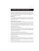
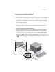
Push-button & keyboard switching In addition to using the on-screen menus, you can switch computer channels in one of three easy ways: via the APC KVM Switch channel push-buttons, with the Scan button or with a simple keyboard sequence. Status indicator LEDs Indicator LEDs give you constant readings on the status of your APC KVM Switch unit. Status, scanning and channel LEDs take the guesswork out of system operation and diagnostics. A typical APC KVM Switch configuration is shown below. 1.
APC KVM Switch Installer/User Guide 2.1 Basic Installation 1. Power down all computers that will be part of your APC KVM Switch system. Connecting your Local Peripherals 2. Locate your keyboard, video monitor and mouse. 3. Plug your VGA monitor cable into the port labeled on the back of your APC KVM Switch or plug your 13W3 monitor cable into the included adapter.
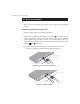
Basic Installation Connecting your Remote Peripherals 4. Plug a standard Category 5 Unshielded Twisted Pair cable (up to 500 feet) into the RJ-45 style modular jack on the rear of the APC KVM Switch. APC C5T or APC P5T cable is strongly recommended to achieve best performance and maximum distance. If you use a different Category 5 cable, make sure it is terminated to the EIA (TIA) 568 B standard, commonly used for 10BaseT Ethernet. 5.
APC KVM Switch Installer/User Guide 7. Connect the Category 5 cable to the modular jack on the rear of the Remote User Receiver. 8. Connect the circular power plug from the wall mount power supply to the power port on the Remote User Receiver. Then plug the power supply into a convenient electrical outlet. Verify that the Remote User Receiver’s POWER light is now lit. Cable Description Length AP9850 AP9851 PS/2 VGA cable PS/2 VGA cable 10 ft. 25 ft. AP9855 USB VGA cable 12 ft.
Basic Installation Connecting Computers to the APC KVM Switch 9. Locate the input cable appropriate to the computer you are connecting. (APC KVM Switch cable types are identified on page 6.) Plug this cable into any numbered channel port on the rear of the APC KVM Switch. The other end of the input cable will have up to three connectors depending on type. The PS/2 mouse connector is designated by a mouse icon.
APC KVM Switch Installer/User Guide 11. Locate the proper power cord and plug it into the IEC power connector on the APC KVM Switch. Make sure that the power switch is off, then plug the other end of the power cord into an appropriate AC wall outlet. This outlet must be near the equipment and easily accessible to allow for unplugging prior to any servicing of the unit. 12. Power-up your APC KVM Switch unit first, then power up all attached computers. 13.
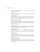
Basic Installation 2.2 Advanced Install Attaching Multiple Switch Units (Please note that cascading can only be done with AP9850, AP9851 or AP9853 cables) 1. Follow steps 1-8 of the Basic Install section for each cascaded unit. 2. Plug the 25-pin “D” connector of your input cable into any available channel port on the rear of your base Switch unit. 3. Plug the 15-pin video connector on the other end of the cable into the port labeled on your first cascading Switch unit.
APC KVM Switch Installer/User Guide 3.1 Basic Operations- Overview Your APC KVM Switch may be operated in a non-secure (no password required) or secure (password required) mode. All units ship defaulted to the non-secure mode. For information on implementing password security, see the “Administrator Functions” section of chapter 4. Computers may be powered-up one-at-a-time or all at once. No operator intervention is required during booting.
Basic Operations 3.2 Keyboard Control The following notational conventions appear throughout this chapter to illustrate commands for operating the APC KVM Switch. Whenever you see one of the symbols listed on the left side of the table, substitute the corresponding steps or values listed on the right side of the table. Convention Key Sequence or Value Enter Command Mode: 1. Press and hold down the ‘Num Lock’ key. 2. Press and release the minus (-) key on the numeric keypad. 3.
APC KVM Switch Installer/User Guide 3.3 Keyboard Switching One of the ways to change the active channel in a non-secured APC KVM Switch system is by entering a short sequence of keystrokes on the keyboard. This is called keyboard, or hot-key, switching. Note: Hot-key switching is only available in the default non-secure state. For more information on secure versus non-secure operation, see the ‘Administrator Functions’ section of Chapter 4. The first set of keystrokes places your system in Command Mode.
On-Screen Display Operations 3.4 System Control and Maintenance The following commands are used for system control and maintenance. Enter the command sequences to perform the actions described in the table below. Key Sequence Action Kn Sets the keyboard scan set where n is a scan set number 1-3. MR If you hot-plug your mouse cable, you may experience a loss of mouse signal. Use this command to restore the signal if you are using a PC with a standard PS/2 mouse driver.
APC KVM Switch Installer/User Guide 4.1 On-Screen Display Operations - Activating OSD Activate on-screen display (OSD) by pressing either of the keyboard Control keys twice within one second. In non-secure mode, this brings up the main OSD Window, “Administrator Channel List”. In secure mode, activating OSD will bring up the “User Login” window. Type in your user name and press Enter. The system administrator should login as “Admin”, “Root” or “Administrator”. Type your password and press Enter.
On-Screen Display Operations 4.2 The OSD Window This window lists all named channels in your APC KVM Switch system. They will be listed alphabetically with their channel addresses and access status beside them. Beside the address there will be a small circle. If the circle is filled, the computer in question is powered on. When in secure mode, only the channels that are accessible to the logged in user will be listed. (See the section ‘Administrator Functions’ for more information.
APC KVM Switch Installer/User Guide 4.3 The Command Menu Once you have activated the main OSD Window, you can open the Command Menu by pressing either of the Control keys twice. The Command Menu options are selected in the same manner as channels in the OSD Window. Scroll the Highlight Bar up and down and press Enter when your selection is highlighted.
On-Screen Display Operations 4.4 Basic Channel Maintenance Basic Channel Maintenance is performed from the Administrator Command Menu, and is available if you are operating in non-secure mode or if you are the system administrator. Here you can add, delete or edit individual channels. Adding Channels APC KVM Switch Add Channel Name Address ID Dwell Time 5 Scan Dwell Time 5 Save Changes Enter = activate ESC = exit THE ADD CHANNEL WINDOW 1.
APC KVM Switch Installer/User Guide Editing Channel Names and Addresses 1. Highlight the channel you wish to change in the main OSD Window. 2. Press the Control key twice to access the Command Menu or press the F2 key once. (If you press F2, skip Step 3.) 3. Select ‘Edit Channel’ from the Command Menu. 4. Enter the new channel name, address, ID Dwell time and Scan Dwell time. Press Enter to accept. 5.
On-Screen Display Operations 4.5 The ID Window The ID Window appears when you change channels and displays the name of the selected channel. This window can be individually configured for each channel in your system. The characteristics of the ID Window can be changed from the Edit Channel Menu. This option is only available if you are operating in non-secure mode or if you are the system administrator. Changing the Size, Color and Position of the ID Window 1.
APC KVM Switch Installer/User Guide 5. Press Enter to accept the changes or press Esc to exit the menu without saving the changes. Setting the ID Window Dwell Time This menu selection lets you set the time that the ID Window remains on screen after a channel switch. Each channel can be configured independently. The default time is set for five seconds. 1. Highlight the channel you wish to change in the main OSD Window. 2.
On-Screen Display Operations 4.6 Administrator Functions The Administrator Functions Menu is accessed from the Administrator Commands Menu. Here, you can setup the administrator and user accounts, enable and disable the setup port and utilize the APC KVM Switch’s FLASH upgrade feature. Differences between Secure and Non-Secure Operating Modes Administrator Account Setting up an administrator account with a password places your system in secure mode. Non-secure systems do not use passwords.
APC KVM Switch Installer/User Guide Creating the Administrator Account 1. Press the Control key twice to access the Command Menu. 2. Select ‘Administrator Functions’ from the Command Menu. 3. Select ‘Setup Administrator’ from the Administrator Menu. 4. Type your password and press Enter. (The password is not case sensitive.) 5. Repeat entry of the password for confirmation. 6.
On-Screen Display Operations 7. Choose the ‘Access Setup’ heading. Here, you will see a listing of all attached servers in the channel list. For each server, choose a level of access for this user by selecting one of the function keys listed on the screen: F5 for no access, F6 for video only or F7 for video and keyboard/mouse capability. The default is set for full access. All changes go into effect as soon as they are made. Press Enter when you have completed your configuration. 8.
APC KVM Switch Installer/User Guide 5.1 Advanced Operation- Multiuser Operation The APC KVM Switch provides advanced features. Primarily, it offers the benefit of adding a Remote User Receiver to provide for a remote user that may be located up to 500 feet away from the APC KVM Switch. The remote user has all the capabilities of the local user and can access any computer attached to the APC KVM Switch system just as if he were sitting in front of it.
Advanced Operation Shared Access If both users need to access the same computer in the base unit, they can ‘share’ access to it through the APC KVM Switch. Sharing means that both consoles can view a computer channel at the same time, but only one can enter data through the keyboard or mouse at any given moment. As soon as the active console stops all keyboard and mouse activity, the other console can take control of the computer.
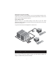
APC KVM Switch Installer/User Guide For example, in the configuration below, two users can access nine computers through three APC KVM Switch units. Independent Access Options 1) Both users can independently access the three computers attached to the base unit at any time. 2) Both users can independently access any computer in a different Switch unit at any time.
Advanced Operation 5.3 Keyboard Translation The APC KVM Switch allows you to use PS/2 or Sun keyboards to operate any type of attached computer. However, when crossing platforms, certain keys will need to be ‘remapped’ in order to provide all of the functions available on the keyboard native to that platform. For example, if you access a Sun workstation with a PS/2 keyboard, you will notice that the PS/2 keyboard does not have the STOP and AGAIN keys that are on a true Sun keyboard.
APC KVM Switch Installer/User Guide Sun keyboards have a power key used to power the workstation on and off. PS/2 keyboards may have a sleep key to place the computer in a stand-by or power saving mode.
Channel Scanning 6.1 Channel Scanning - Choosing a scan method APC KVM Switch's scanning feature allows you to automatically monitor, or scan, your computer channels without intervention. When keyboard activity is detected, scanning is suspended until all keyboard activity stops. Scanning then resumes with the next channel in sequence. The length of time each channel remains on the screen, or dwell time, is configurable and can be changed at any time.
APC KVM Switch Installer/User Guide 6.2 Turning Scanning On and Off From the OSD menu. 1. From the main OSD Window, press the Control key twice to access the Command Menu. 2. Toggle ‘Scanning is OFF’, ‘Scanning by Name’, ‘Scanning by Address’ or ‘Scanning by List’ from the menu. This is a toggle option - only one scanning option will show on the menu at any one time. Selecting ‘by Name’ will scan channels alphanumerically by name, ‘by Address’ will scan channels numerically by channel address. 3.
Channel Scanning 6.3 Scanning by List Scanning by list allows you to create a customized scanning order for the switch to follow. Any active channel in the system can be scanned in any order, as many times as desired. To configure the scan list, open the main OSD window by pressing either of the Control keys twice. Press them twice more to access the Command Menu. From the Command Menu, use your arrow keys to highlight ‘Setup Scan List’ and press the Return key.
APC KVM Switch Installer/User Guide 7.1 Specifications Mechanical Height: 1.7" (4.5 cm) Width: 17.2" (43.7 cm) Depth: 6.5" (16.51 cm) Weight: 4.8 lbs (2.
Appendices 7.2 Specifications for Remote User Receiver (AP9279) Mechanical Height: 1.9" (4.8 cm) Width: 8.1" (20.6 cm) Depth: 4.8" (12.2 cm) Weight: 1 lb. (0.
APC KVM Switch Installer/User Guide 7.3 FLASH Upgrading To upgrade the FLASH code on your APC KVM Switch, you will first need to obtain the latest FLASH firmware revision from APC. It is available online at www.apc.com. Next you will need a serial cable (available at most electronics stores) to connect a computer to your APC KVM Switch. Simply connect the serial cable between the SETUP port on your APC KVM Switch to the serial port on the computer.
Appendices Configure your terminal program to the following settings: 38,400 Baud 8 Bits No Parity 1 Stop Bit No Flow Control Activate the OSD menu on your APC KVM Switch by tapping the Control key twice. Enter Control twice more to activate the Administrator Commands screen and then select Administrator Functions. Use the down arrow key to highlight the menu selection for FLASH Upgrade, then hit Enter. A menu screen will appear and ask if you wish to continue.
APC KVM Switch Installer/User Guide 7.4 Troubleshooting APC’s Technical Support staff is ready to assist you with any installation or hardware problems you encounter with your APC product. If a problem should develop, follow the steps below for the fastest possible service: 1. Check the troubleshooting tables below to see if the problem can be resolved by following the procedures outlined. 2. If you are unable to find a resolution, recreate the problem when possible.
Appendices Symptom Action Unable to hot-key switch to a channel Check the power indicator on the OSD screen to ensure that the system in question is powered. Verify that you are not in secure mode. (No lock symbol on OSD screen.) Verify that you are in hot-key mode by checking to see if the green status LED is blinking. If it is not, press escape and try going into command mode again. If the problem persists, contact APC Technical Support.
APC KVM Switch Installer/User Guide Symptom Action Mouse is inoperable on one computer channel If the mouse is inoperable on a channel, try the mouse reset command or with that PC selected. (For instructions on command mode, see ‘Basic Operations’.) Verify that the cables from the computer to the APC KVM Switch are connected properly. Make sure that you have keyboard/mouse privileges for that channel. Verify that the mouse driver and application are configured properly for mouse support.
Appendices Symptom Action Keyboard is inoperable on one computer channel If keyboard does not function on one channel, verify that the cables from the computer to the APC KVM Switch are connected properly. If you are operating in secure mode, verify your keyboard and mouse privileges. Verify that the keyboard works properly connected directly to the computer. If the problem persists, contact APC Technical Support.
APC KVM Switch Installer/User Guide Symptom Action OSD menu does not “pop-up” Verify that you are pressing the Control key twice within one second. If the problem persists, contact APC Technical Support. Unable to change channels using OSD Verify that the channel is powered. Check the address configured in OSD. If the computer is powered and the address is correct, call APC Technical Support. Administrator password is forgotten Call Technical Support.
Appendices 7.4 If Problems Persist For problems not covered in the earlier troubleshooting chart, or if the problem persists, follow this procedure: 1. Note the serial number and date of purchase of the APC KVM Switch. Contact Customer Service at the phone number or address on the back cover of this manual. 2. Be prepared to provide a description of the problem. A technician will help solve the problem over the phone, if possible, or will give you a Return Material Authorization (RMA) number. 3.
Limited Warranty American Power Conversion (APC) warrants its products to be free from defects in material and workmanship for a period of two years from the date of purchase. Its obligation under this warranty is limited to repairing or replacing, at its own sole option, any such defective products. To obtain service under warranty you must obtain a Return Material Authorization (RMA) number from APC or an APC service center.
Life Support Policy General policy As a general policy, American Power Conversion (APC) does not recommend the use of any of its products in the following situations: • life support applications where failure or malfunction of the APC product can be reasonably expected to cause failure of the life support device or to significantly affect its safety or effectiveness. • direct patient care.
APC Worldwide Customer Support Customer support for this or any other APC product is available at no charge in any of the following ways: • Visit the APC Web site to find answers to frequently asked questions (FAQs), to access documents in the APC Knowledge Base, and to submit customer support requests. - http://www.apcc.com (Corporate Headquarters) Connect by links to APC Web pages for specific countries and regions, each of which provides customer support information. - http://www.apcc.