Installation and Quick Configuration Environmental Manager Main Module AP9340
This manual is available in English on the enclosed CD. Dieses Handbuch ist in Deutsch auf der beiliegenden CD-ROM verfügbar. Este manual está disponible en español en el CD-ROM adjunto. Ce manuel est disponible en français sur le CD-ROM ci-inclus. Questo manuale è disponibile in italiano nel CD-ROM allegato. 本マニュアルの日本語版は同梱の CD-ROM からご覧になれ ます。 Instrukcja Obsługi w jezyku polskim jest dostepna na CD. Данное руководство на русском языке имеется на прилагаемом компакт-диске.
Contents Installation ............................................ 1 Preliminary Information. . . . . . . . . . . . . . . . . . .1 Overview . . . . . . . . . . . . . . . . . . . . . . . . . . . . . 1 Inventory . . . . . . . . . . . . . . . . . . . . . . . . . . . . . 1 Additional options . . . . . . . . . . . . . . . . . . . . . 2 Additional documentation . . . . . . . . . . . . . . . 2 Please recycle . . . . . . . . . . . . . . . . . . . . . . . . 2 Receiving inspection . . . . . . . . . . . . . . . . . .
Accessing a Configured Main Module . . . . . 20 Overview . . . . . . . . . . . . . . . . . . . . . . . . . . . . .20 Web interface . . . . . . . . . . . . . . . . . . . . . . . . .20 Telnet and SSH . . . . . . . . . . . . . . . . . . . . . . .21 Simple Network Management Protocol (SNMP) 21 FTP and SCP . . . . . . . . . . . . . . . . . . . . . . . . .22 Modbus . . . . . . . . . . . . . . . . . . . . . . . . . . . . . .22 Recovering from a Lost Password . . . . . . . . 23 Specifications ....................
Installation Preliminary Information Overview Use the Environmental Manager Main Module to monitor and control the environment through peripheral devices, including temperature and humidity sensors and environmental control devices. You can increase the number of monitored racks by adding Temperature/Humidity Modules (TH Modules) to your configuration.
Additional options The following options are available for the Main Module: • TH Module (AP9341) • Temperature Sensor (AP9335T) • Temperature/Humidity Sensor (AP9335TH) • Temperature Sensor with Digital Display (A-Link) (AP9520T) • Temperature/Humidity Sensor with Digital Display (A-Link) (AP9520TH) • Alarm Beacon (AP9324) • Door Switch Kit (AP9513) • Power Supply (AP9505i) Additional documentation For additional information about management interfaces, user accounts, customizing setup, configuration utilit
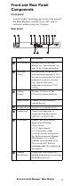
Front and Rear Panel Components Front panel Use the toolless mounting pegs on the front panel of the Main Module to install it in an APC rack or enclosure without using any U-spaces. 2 3 4 –+ –+ 1 –+ –+ + G NC N 2412 N OO C D M GD D N0 1 D + Environmental Manager aem0048a Rear panel Item Description AC Line Inlet Provides power to the Main Module; see “Specifications” on page 24 for voltage information. Switched Outlet Provides power to a device at a total maximum amperage of 10 A.
4 Item Description 10/100 Base-T Network Port Connect the Main Module to the network; Status and Link LEDs indicate network traffic. • Status LED—blinks orange and green at start-up; indicates the status of the network connection (solid green—IP address established; blinking green— attempting to obtain an IP address). • Link LED—blinks to indicate network traffic (green—operating at 10 mbps; orange—operating at 100 mbps).
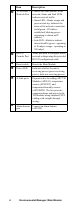
Installation—Main Module You can install the Main Module in the front or the rear of the rack or enclosure, using either the rack-mount option, which uses 1 U of rack space, or the toolless peg-mount option, which does not use any U-spaces. (The toolless peg-mount option is available only with APC NetShelter® VX and SX racks and enclosures). Toolless peg-mount installation 1 . Slide both mounting pegs into the holes located in the cable channel in the rear panel of the rack. aem0049a 2 .
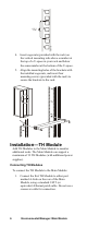
7 6 5 ns0014a 1U 4 . Insert cage nuts (provided with the rack) on the vertical mounting rails above a number at the top of a U-space in your rack and below the same number at the bottom of the U-space. pdu0080a 5 . Align the mounting holes of the brackets with the installed cage nuts, and insert four mounting screws (provided with the rack) to secure the brackets to the rack. Installation—TH Module Add TH Modules to the Main Module to monitor additional racks.
Note: A-Link is an APC proprietary CAN (Controller Area Network) bus. Devices compatible with A-Link are not Ethernet devices and cannot coexist on an Ethernet bus with other networking devices, such as hubs and switches. 2 . Connect the cable from the Main Module to the top A-Link connector labeled (indicating “input”) on the TH Module. Connect the bottom A-Link connector labeled (indicating “output”) to the next TH Module. 3 . Plug an APC terminator into the unused A-Link port at each end of the string.
CAT5 (or equivalent) cable connecting to the next TH Module in the cascading configuration. This port may be used to link to a TH Module or to plug in an APC terminator. Adding power supplies Warning: The first time a TH Module receives power, it requests a unique identification address from the Main Module. It uses this address to communicate with the Main Module.
How to wire Modbus The Modbus interface supports 2-wire RS-485, plus ground. Modbus can be configured to communicate at either 9600 or 19200 bps. The default setting is 9600 bps. Modbus requires both termination and polarization resistors at the bus master. Each end of the bus requires a 150-ohm resistor, and the bus also requires a 400–650-ohm resistor from D1 to +5 Vdc and from D0 to GND.
To install a sensor on the vertical rail of an APC rack: aem0184a 1 . Determine a location on the vertical rail that will allow you to route and secure the 4-m (13-ft) cord neatly. 2 . Peel the backing off the adhesive side of a sensor mount, and press the cable mount firmly to the vertical rail. 3 . Thread a tie wrap through the sensor mount. 4 . Secure the sensor to the sensor mount with the tie. Tighten and trim the tie wrap. 5 .
To install a sensor on the door of an APC rack: 1 . For optimal sensor performance, install the sensor near the top of the rack door. The bottom of the rack door will not accurately represent the temperature of the air in the room. aem0073a 2 . Thread a tie wrap through the door holes, skipping one hole in the middle. –If you have a temperature/humidity sensor, place the sensor in the middle of the tie wrap, and pull the tie wrap around a ridge on the sensor casing.
6 . To secure the sensor cord, choose a location near the middle of the door frame, and repeat step 5. Note: If you use more than one sensor per rack, route the sensor cord farthest from the middle of the rack first. When routing the sensor cord closest to the middle of the rack, secure all sensor cords in the tie wrap. aem0076a 7 . With the door fully open, thread the sensor cords through the opening in the front post of the rack. 8 .
Alarm beacon (optional) 1 . Install the alarm beacon in a visible position either on the roof of the rack or inside the rack. aem0061a 2 . If you install the beacon on the roof, route its cable through the provided holes, as shown in the following illustration. 3. Plug the cable into the Alarm Beacon port. 4 . You can extend the cable to a maximum of 100 m (330 ft), using RJ-45 couplings and standard CAT5 cables.
User Inputs aem0067a + + 2-Wire 4–20 mA Sensor + - User Inputs aem0064a + + COM + PWR - 4-Wire 4–20 mA Sensor 14 Environmental Manager: Main Module
Quick Configuration Note: Disregard the procedures in this section if you have APC InfraStruXure Central or InfraStruXure Manager as part of your system. See the documentation for your InfraStruXure device for more information.
APC Device IP Configuration Wizard You can use the APC Device IP Configuration Wizard at a computer running Windows® 2000, Windows Server 2003, or Windows XP to configure the basic TCP/IP settings of the Main Module. Note: Most software firewalls must be temporarily disabled for the Wizard to discover unconfigured Main Modules. 1 . Insert the Utility CD into a computer on your network. 2 . If autorun is enabled, the user interface of the CD starts when you insert the CD. Otherwise, open the file contents.
BOOTP. For the Main Module to use a BOOTP server to configure its TCP/IP settings, it must find a properly configured RFC951-compliant BOOTP server. 1 . In the BOOTPTAB file of the BOOTP server, enter the Main Module’s MAC address, IP address, subnet mask, and default gateway, and, optionally, a bootup file name. For the MAC address, look on the bottom of the Main Module or on the Quality Assurance slip included in the package. 2 .
where –the first byte (01) is the code –the second byte (04) is the length –the remaining bytes (31 41 50 43) are the APC cookie See your DHCP server documentation to add code to the Vendor Specific Information option. To disable the requirement that a DHCP offer include the APC cookie, use the DHCP Cookie Is setting in the control console: Network>TCP/IP> Boot Mode> DHCP only>Advanced>DHCP Cookie Is.
MAC address of 00 c0 b7 63 9f 67, use one of the following commands: –Windows® command format: arp -s 156.205.14.141 00-c0-b7-63-9f-67 –LINUX command format: arp -s 156.205.14.141 00:c0:b7:63:9f:67 For the MAC address, look on the bottom of the Main Module or on the Quality Assurance slip included in the package. 2 . Use Ping with a size of 113 bytes to assign the IP address defined by the ARP command. For example: –Windows command format: ping 156.205.14.141 -l 113 –LINUX command format: ping 156.205.
Accessing a Configured Main Module Overview After the Main Module is running on your network, you can access the configured Main Module through the following interfaces: • Web interface (HTTP or HTTPS protocol) • Telnet or Secure SHell (SSH) • SNMP • FTP or Secure CoPy (SCP) to upgrade firmware • Modbus For more information on the interfaces, see the Environmental Manager: Main Module User’s Guide. Web interface Use Microsoft® Internet Explorer® 5.
Telnet and SSH You can access the control console through Telnet or Secure SHell (SSH), depending on which is enabled. Select the Administration tab, the Network option on the top menu bar, and then the access option under Console on the left navigation menu. By default, Telnet is enabled. Enabling SSH automatically disables Telnet. Telnet for basic access. Telnet provides the basic security of authentication by user name and password, but not the high-security benefits of encryption.
Note: To use SNMPv3, you must have a MIB program that supports SNMPv3. The Main Module supports only MD5 authentication and DES encryption. SNMPv1 and SNMPv3. To use InfraStruXure Central or InfraStruXure Manager to manage the Main Module on the public network of an InfraStruXure system, you must have SNMPv1 enabled in the unit interface. Read access allows InfraStruXure devices to receive traps from the Main Module. Write access is required while you set the InfraStruXure device as a trap receiver.
Recovering from a Lost Password You can use a local computer (a computer that connects to the Main Module through the serial port) to access the control console. 1 . Select a serial port at the local computer, and disable any service that uses that port. 2 . Connect the provided RS-232 configuration cable to the selected port on the computer and to the RS-232 console port at the Main Module. 3 .
Specifications Environmental Manager Main Module Electrical Input voltage, nominal 100–240 Vac; 50/60 Hz Maximum total current draw 10 A Maximum output voltage Defined by input voltage Maximum output current 10 A Physical Dimensions (H x W x D) 4.42 x 43.20 x 4.42 cm (1.74 x 17.00 x 1.74 in) Weight 1.10 kg (2.50 lb) Shipping weight 2.70 kg (6.00 lb) Shipping dimensions (H x W x D) 6.70 x 45.00 x 22.50 cm (2.62 in x 17.75 x 8.
Sensors Temperature/Humidity (AP9335TH) Temperature accuracy ±2ºC (±3ºF), from 0 to 40ºC (32 to 104ºF) Humidity accuracy ±4% RH, 20 to 90% RH, at 25ºC (77ºF) ±8% RH, 30 to 80% RH, from 15 to 30ºC (59 to 95ºF) Sensor operating temperature –10 to 70ºC (14 to 159ºF) User input response time 200 mS Maximum length of cable 15.
Product Information Two-Year Factory Warranty This warranty applies only to the products you purchase for your use in accordance with this manual. Terms of warranty APC warrants its products to be free from defects in materials and workmanship for a period of two years from the date of purchase. APC will repair or replace defective products covered by this warranty.
CONNECTION WITH THE PRODUCTS. THE FOREGOING WARRANTIES AND REMEDIES ARE EXCLUSIVE AND IN LIEU OF ALL OTHER WARRANTIES AND REMEDIES. THE WARRANTIES SET FORTH ABOVE CONSTITUTE APC’S SOLE LIABILITY AND PURCHASER’S EXCLUSIVE REMEDY FOR ANY BREACH OF SUCH WARRANTIES. APC WARRANTIES EXTEND ONLY TO PURCHASER AND ARE NOT EXTENDED TO ANY THIRD PARTIES.
support device or to affect significantly its safety or effectiveness. • In direct patient care. APC will not knowingly sell its products for use in such applications unless it receives in writing assurances satisfactory to APC that (a) the risks of injury or damage have been minimized, (b) the customer assumes all such risks, and (c) the liability of APC is adequately protected under the circumstances.
Radio Frequency Interference Changes or modifications to this unit not expressly approved by the party responsible for compliance could void the user’s authority to operate this equipment. USA —FCC This equipment has been tested and found to comply with the limits for a Class A digital device, pursuant to part 15 of the FCC Rules. These limits are designed to provide reasonable protection against harmful interference when the equipment is operated in a commercial environment.
Australia and New Zealand Attention: This is a Class A product. In a domestic environment this product may cause radio interference in which case the user may be required to take adequate measures. European Union This product is in conformity with the protection requirements of EU Council Directive 89/336/EEC on the approximation of the laws of the Member States relating to electromagnetic compatibility.
APC Worldwide Customer Support Customer support for this or any other APC product is available at no charge in any of the following ways: • Visit the APC Web site to access documents in the APC Knowledge Base and to submit customer support requests. – www.apc.com (Corporate Headquarters) Connect to localized APC Web sites for specific countries, each of which provides customer support information. – www.apc.com/support/ Global support searching APC Knowledge Base and using e-support.