Title Page Web/SNMP Management SmartSlot Card AP9606 User’s Guide
Thank You! Thank you for selecting the APC Web/SNMP Management SmartSlot Card. It has been designed for many years of reliable, maintenance-free service. APC is dedicated to the development of high-performance electrical power conversion and control products. We hope that you will find this product a valuable, convenient addition to your system. Please read this manual! It provides important configuration and operating instructions that will help you get the most from your Management Card.
Web/SNMP Management SmartSlot Card Contents Introduction . . . . . . . . . . . . . . . . . . . . . . . . . . . . . . . . . 8 Product Description . . . . . . . . . . . . . . . . . . . . . . . . . . . . . 8 Functionality—8 Management Card versions—9 Initial set-up—9 Network management features—10 Internal Management Features . . . . . . . . . . . . . . . . . . . . 11 Login control—11 Types of user accounts—11 Front Panel . . . . . . . . . . . . . . . . . . . . . . . . . . . . . . . . . .
Contents Web Interface . . . . . . . . . . . . . . . . . . . . . . . . . . . . . . . 20 Introduction . . . . . . . . . . . . . . . . . . . . . . . . . . . . . . . . . 20 Web menu options—20 Supported Web browsers—20 How to Log In . . . . . . . . . . . . . . . . . . . . . . . . . . . . . . . . 21 Overview—21 URL address formats—21 Status Summary Page . . . . . . . . . . . . . . . . . . . . . . . . . . . 22 Example Web page—22 Status and identification information—22 Menu Frame . . . . . . . . . . . . . . .
Contents System Menu . . . . . . . . . . . . . . . . . . . . . . . . . . . . . . . . 30 Introduction . . . . . . . . . . . . . . . . . . . . . . . . . . . . . . . . . 30 Overview—30 Menu options—30 Option Settings . . . . . . . . . . . . . . . . . . . . . . . . . . . . . . . 31 User Manager—31 Identification—31 Date & Time—32 File Transfer—32 Tools—32 Links—33 About System—33 Device Manager Menus . . . . . . . . . . . . . . . . . . . . . . . . 34 Introduction . . . . . . . . . . . . . . . . . . . . . .
Contents UPS PowerChute network shutdown Option. . . . . . . . . . 48 Overview—48 Parameters—48 Environment Menu Options . . . . . . . . . . . . . . . . . . . . . . 49 Probe status—49 Contact status—49 Probe settings—49 Contact settings—49 Events Menu . . . . . . . . . . . . . . . . . . . . . . . . . . . . . . . . 50 Introduction . . . . . . . . . . . . . . . . . . . . . . . . . . . . . . . . . 50 Overview—50 Menu options—50 Event Log. . . . . . . . . . . . . . . . . . . . . . . . . . . . . . . . . . . .
Contents Security . . . . . . . . . . . . . . . . . . . . . . . . . . . . . . . . . . . . 67 Security Features . . . . . . . . . . . . . . . . . . . . . . . . . . . . . . 67 Planning and implementing security features—67 Port assignments—67 User names, passwords and community names— 67 Authentication . . . . . . . . . . . . . . . . . . . . . . . . . . . . . . . . 68 Authentication versus encryption—68 MD5 authentication (Web interface)—68 Firewalls—68 Summary of access methods—69 Troubleshooting . . . .
Web/SNMP Management SmartSlot Card Introduction Product Description Functionality American Power Conversion’s Web/SNMP Management SmartSlot Card (APC part number AP9606) is a web-based UPS Management product that uses multiple, open standards such as Telnet, HTTP, and SNMP to provide full management of UPS systems.
Introduction Product Description continued Management Card versions The Management Card (v3.0.0) has firmware that provides an APC operating system (AOS) layer (aos300.bin), and one of three available application layers. Which application firmware a Management Card uses depends on the UPS it supports. • • • Symmetra Power Array (sy300.bin) Smart-UPS and Matrix-UPS (sumx300.bin) Silcon DP300E series UPS (dp3e300.
Introduction Product Description continued Network management features The figure below identifies and describes the network management applications that can work with a UPS that connects to the network through a Management Card.
Introduction Internal Management Features Overview The Management Card has two internal interfaces, the Control Console and the Web interface, which provide menus with options that allow you to manage the UPS, an Environmental Monitoring SmartSlot Card, and the Management Card. The Management Card’s SNMP interface allows you to use an SNMP browser with the APC MIB (PowerNet MIB) to manage the UPS and an Environmental Monitoring SmartSlot Card.
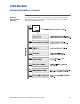
Introduction Front Panel Features The front panel has the following features: • Reset button • 10Base-T network cable connector • Link-RX/TX LED • Status LED Reset Button. Allows you to reset the Management Card while power is on. 10Base-T Port. Used to connect the Management Card to the Ethernet network. Link-RX/TX LED. Indicates the network status. Condition Description Off The device which connects the Management Card to the network is turned off or it is not operating correctly.
Introduction Watchdog Features Overview The Management Card is designed to recover from unanticipated inputs. Through the use of internal, system-wide watchdog mechanisms, the Management Card can detect most internal problems and reboot itself to recover. Network interface watchdog mechanism The Management Card implements numerous internal watchdog mechanisms to protect itself from becoming inaccessible over the network.
Web/SNMP Management SmartSlot Card Control Console Introduction Overview The Control Console provides a set of menus that you can use to manage the Management Card, its UPS, and an Environmental Monitoring SmartSlot Card, from a local computer or over the network. Menu structure The Control Console menus list options by number and name. To use an option, type the option’s number and press ENTER, then follow any on-screen instructions.
Control Console How to Log In Overview You can use either a local (serial) connection, or a remote (Telnet) connection with a computer on the Management Card’s subnet to access the Control Console. Use case-sensitive User Name and Password entries to log in (by default, apc and apc, for an Administrator, or device and apc, for a Device Manager). For information about the screen that appears when you log into the Control Console, see Main Screen on page 17.
Control Console How to Recover from a Lost Password Overview If the User Name or Password becomes unknown, you can use a local computer to restore access to a Management Card that uses the APC AOS module, version 3.0 (or later). The latest AOS version is available at the APC web site (www.apcc.com). Recovery procedure To recover from a lost Password or User Name, do the following: 1. Select a serial port at the computer to be used for a terminalemulation connection with the Management Card. 2.
Control Console Main Screen Example main screen The following is an example of the screen that appears when you log into the Control Console. Status and identification information In addition to a menu (described in Control Console Menu on page 19), the main screen provides the following information: • Two fields identify the APC operating system (AOS) and application (APP) firmware versions.
Control Console Main Screen continued Status and identification information, continued • Two fields identify when you logged in, by Date and Time. Date Time • : 05/10/2000 : 10:39:16 Note: For information about how to change the Date and Time values, see System Menu on page 30. A User field identifies whether you logged in as an Administrator or Device Manager. User • : Administrator An Up Time field reports how long the Management Card has been running since it was last turned on or reset.
Control Console Control Console Menu Overview The Control Console menu has four options, three of which provide access to the Control Console’s management features: 1234- Device Manager Network System Logout Note: When you log in as Device Manager, you can access only the event log and the Device Manager menus. Device Manager option This option accesses the Device Manager menu.
Web/SNMP Management SmartSlot Card Web Interface Introduction Overview Unless the Web interface is disabled by the Web menu’s Access option, you can use a supported Web browser to manage a UPS, an Environmental Monitoring SmartSlot Card, and the Management Card. Web menu options Two Web menu options affect access to the Web interface. • • Access: Enables or disables the Web interface. Port: Defines the Web-server port (80, by default) used for the Web interface.
Web Interface How to Log In Overview You can use a Management Card’s DNS name or System IP address for the URL address of the Web interface. Use your case-sensitive User Name and Password settings to log in (by default, apc and apc, for an Administrator, or device and apc, for a Device Manager). For information about the Web page that appears when you log into the Web interface, see Status Summary Page on page 22.
Web Interface Status Summary Page Example Web page The following is an example of the “Status Summary” page that appears when you log into the Web interface. Status and identification information In addition to the menu frame elements described in Menu Frame on page 23, the “Status Summary” page provides the following information: • • • • • • A UPS model and name section reports the UPS status. An Environment section reports the status of the Environmental Monitoring SmartSlot Card.
Web Interface Menu Frame Overview When you log into the Web interface as an Administrator, the navigation bar (left frame) includes the following elements: • • • • • • • • • • Note: Events menu The Management Card’s IP address An Events menu A UPS menu which uses the UPS model for its name (Smart-UPS 700, in the example on page 22) An Environment menu A Network menu A System menu A Logout option A Help menu Logo and text links to Interactive Assistant Three user-definable User Links The Environment menu
Web Interface Menu Frame continued Network menu This menu’s options allow you to do the following: • • Configure new TCP/IP settings for the Management Card. Define settings that affect the use of TFTP, FTP, Telnet, SNMP, and Email. Note: For information about how the Network menu’s Web options affect access to the Web interface, see Web menu options on page 20. For information about how to use this menu, see Network Menu on page 26.
Web Interface Menu Frame continued Interactive Assistant APC Interactive Assistant brings APC customer service to the Web. When you select Interactive Assistant, the Management Card transmits information about itself, and its UPS, to the APC Interactive Assistant server. The server informs you if the UPS has a bad battery. The “Interactive Assistant” Web page provides links to more information about the Management Card and the UPS, as well as links to relevant pages at the APC Web site.
Web/SNMP Management SmartSlot Card Network Menu Introduction Overview The Network menu provides access to the options you use to configure the Management Card’s network settings. Note: Menu options Only an Administrator has access to the System menu. For information about the settings available for the Network menu options, see the following descriptions: • • • TCP/IP on page 27 DNS on page 27 Ping utility on page 27 • • • • • Note: The Ping utility option is available only in the Control Console.
Network Menu Option Settings TCP/IP This option allows you to enable or disable BOOTP, and when BOOTP is disabled, define the three TCP/IP settings that the Management Card needs to operate on the network.
Network Menu Option Settings continued TFTP Client Use this option to define the IP address of the TFTP server used to download configuration files (0.0.0.0, by default). Note: FTP Client Use this option to define the IP address of the FTP server used to download configuration files (0.0.0.0, by default), as well as the casesensitive User Name and Password settings (apc is the default for both) used to protect FTP access.
Network Menu Option Settings continued SNMP An Access option (the Settings option in the Control Console) enables (by default) or disables SNMP. When SNMP is enabled, the Access Control settings allow you to control how each of the four available SNMP channels is used.
Web/SNMP Management SmartSlot Card System Menu Introduction Overview The System menu provides access to the options that you use to do the following tasks: • • • • • Note: Menu options Configure system identification, date and time settings, and Administrator and Device Manager access. Download configuration files. Reset or reboot the Management Card. Define the URL links available in the Web interface Access hardware and firmware information about the Management Card.
System Menu Option Settings User Manager Use this option to define the access values shared by the Control Console and the Web interface, and the authentication used to access the Web interface. Setting Definition Auto Logout Defines (in minutes) how long someone logged into the Control Console or Web interface can be inactive before that user is automatically logged out (3 minutes by default). Authentication The Basic setting (default) causes the Web Interface to use standard HTTP 1.
System Menu Option Settings continued Date & Time Use this option to change the Date (MM/DD/YYYY format) or Time (HH:MM:SS format) used by the Management Card. File Transfer The Web interface identifies the IP addresses for the remote TFTP and FTP servers, as well as the case-sensitive User Name and Password settings used for FTP (apc, is the default for both). To use TFTP and FTP for file transfers, do the following: 1. Define the file name in the Filename field, and click Apply. 2.
System Menu Option Settings continued Links Use this option, which is only available in the Web interface, to configure the three User Links, the URL address used by the APC logo, and the URL address used by the various Interactive Assistant links. Setting Definition User Links Name Defines the link name (up to 3) that appears on the menu frame. URL Defines the URL address used by each link (http:// www.apcc.com is the default for all three user links).
Web/SNMP Management SmartSlot Card Device Manager Menus Introduction Overview Two Device Manager menus appear in the Control Console and Web interface. • • UPS menu options A UPS menu, which uses the UPS model for its name, provides the options that you use to manage the UPS. For more information about this menu, see UPS menu options below.
Device Manager Menus UPS Status Options Overview The Status options provide access to the information described in the following sections: • • • • • Detailed UPS status on this page Input voltage on page 36 Output voltage on page 37 Fault tolerance (Symmetra Power Array) on page 38 Battery on page 39 Note: No description is provided for the self-explanatory About UPS status fields.
Device Manager Menus UPS Status Options continued Input voltage All UPS models report the input voltage and frequency. A Silcon DP300E series UPS, which identifies the input voltage values for all three phases, also reports the current (amperage) provided by the input voltage. Note: In the Control Console, use the Detailed UPS Information option to access the Minimum and Maximum Input Voltage status for a Symmetra Power Array or Silcon DP300E series UPS.
Device Manager Menus UPS Status Options continued Output voltage The output voltage status information displayed depends on the UPS model. Smart-UPS/Matrix-UPS. Four status fields report on the output from a Smart-UPS or Matrix-UPS. Note: In the Control Console, the output voltage fields for a Smart-UPS or Matrix-UPS are all displayed above the UPS menu. Status Field Definition Output Voltage How much AC voltage the UPS is providing to its attached equipment.
Device Manager Menus UPS Status Options continued Output voltage, continued Silcon DP300E. Five status fields report the output values for a Silcon DP300E series UPS. Note: In the Control Console, use the Detailed UPS Information option to access the Peak Output Current status. Status Field Fault tolerance (Symmetra Power Array) Definition Output Voltage How much AC voltage the UPS is providing to its attached equipment for each phase.
Device Manager Menus UPS Status Options continued Battery The following table uses footnotes to indicate which fields are shared by which UPS models. Only one battery-related status field (Runtime Remaining) is shared by all UPS models. Note: In the Control Console, use the Detailed UPS Information option to access the Number of External Batteries, Number of Bad Batteries, and Actual Battery Bus Voltage status for a Symmetra Power Array.
Device Manager Menus UPS Diagnostics Options Overview There are two types of diagnostics options you can use with a Smart-UPS, Matrix-UPS, or Symmetra Power Array (a Silcon DP300E has no diagnostic options): • Options which cause a specified test to occur immediately. • A scheduling option which controls when a UPS self-test occurs. How these options are accessed depends on whether you use the Web interface or Control Console. Diagnostics The following table describes the available diagnostics options.
Device Manager Menus UPS Control Options Silcon DP300E series UPS Three control actions are available for a Silcon DP300E series UPS. Note: Only the Reset UPS to Defaults option is available by default. Action Definition Turn UPS Off Turns the UPS off after the expiration of the Shutdown Delay described in the table in Shutdown parameters on page 45. Turn UPS Off Gracefully Causes the UPS to turn off after PowerChute plus has time to shut down the server’s operating system safely.
Device Manager Menus UPS Control Options continued Smart-UPS, Matrix-UPS, and Symmetra Power Array The Smart-UPS, Matrix-UPS, and Symmetra Power Array Control options are identical, with one exception: Symmetra Power Array and Matrix-UPS use a bypass mode; Smart-UPS does not. Note: For information about the Sleep Time setting which appears in the Web interface’s “Control” and “Configuration” pages, see the table in Shutdown parameters on page 45.
Device Manager Menus UPS Configuration Options Overview The UPS menu’s Configuration option provides access to the configurable parameters described in the following sections: • Utility line settings on this page • Alarm thresholds (Symmetra Power Array) on page 44 • Shutdown parameters on page 45 • General settings on page 46 • Battery on page 39 Utility line settings The Utility Line settings and their values differ by UPS model.
Device Manager Menus UPS Configuration Options continued Utility line settings, continued Symmetra Power Array. The following table describes the Symmetra Power Array Utility Line settings. Setting Alarm thresholds (Symmetra Power Array) Definition Output Voltage The nominal AC voltage level for the UPS output. Vout Reporting How the UPS scales its output voltage readings. Output Frequency Range The nominal value for the frequency used by the output voltage.
Device Manager Menus UPS Configuration Options continued Shutdown parameters Symmetra Power Array, Smart-UPS, and Matrix-UPS use all five Shutdown Parameter settings. A Silcon DP300E series UPS uses only Low-Battery Duration and Shutdown Delay. Note: In the Control Console, use the Configuration menu’s Battery option to access the Return Battery Capacity setting.
Device Manager Menus UPS Configuration Options continued General settings The available General Settings differ by UPS model. Four General Settings are available for Smart-UPS. The first two settings (UPS Name and Last Battery Replacement) are available for all UPS models. The third setting (Audible Alarm) is also available for Matrix-UPS. Note: In the Control Console, use the Configuration menu’s Battery option to access the Last Battery Replacement and External Batteries settings.
Device Manager Menus Module Status Option (Symmetra Power Array) Menu options A Module Status option in the Web interface and a Module Diagnostics & Information option in the Control Console provide access to status, hardware, and diagnostics information about the Symmetra Power Array modules. Note: Module status For each module, the Module Diagnostics & Information option in the Control Console also provides raw data that is used by APC engineers and technical support to troubleshoot hardware problems.
Device Manager Menus UPS PowerChute network shutdown Option Overview A PowerChute option in the Web interface’s UPS menu allows you to use the APC PowerChute network shutdown utility to shut down servers on your network that are using any client-version of PowerChute network shutdown. For more information about PowerChute network shutdown, see the following documents provided in the .\pcns directory on the APC Web/ SNMP Management Card utility CD: • PowerChute network shutdown Installation Guide (Install.
Device Manager Menus Environment Menu Options Overview The Status option (Web interface) and the Threshold and Contact Details option (Control Console) provide access to the status information about the probes and contacts. The Status option in the Web interface also accesses the firmware information for the Environmental Monitoring SmartSlot Card. In the Control Console, the firmware information is accessed through the About Environmental Monitor option.
Web/SNMP Management SmartSlot Card Events Menu Introduction Overview The Events menu provides access to the options that you use to do the following tasks: • • • • Menu options Access the event log. Define the actions to be taken when an event occurs, based on the severity level of that event. – Event logging – SNMP trap notification – Email notification Note: You can use only the Web interface to define which events will use which actions. You can also use an evntlist.
Events Menu Event Log Overview The Management Card supports event logging for all UPS application firmware modules (sumx300.bin, sy300.bin, and dp3e300.bin.) This allows you to record and view UPS, Environmental Monitoring SmartSlot Card, and Management Card events. You can use any of the following to view the event log: • Web interface • Control Console • FTP Logged events By default, any event which causes an SNMP trap is logged, except for SNMP authentication failures.
Events Menu Event Log continued FTP You can use FTP to retrieve a text version (event.txt) of the event log. • • • The event.txt file is Tab-delineated so that it can be easily imported into any spreadsheet application. It reports as many as 5000 events that occurred since the log was last deleted. It includes information that is not in the Web interface and Control Console event log displays. – The version of the event.txt file format (first field). – The Date and Time the event.txt file was retrieved.
Events Menu Event Actions (Web Interface only) Overview The Actions option is available only in the Web interface’s Events menu. It allows you to select whether the following actions are enabled or disabled for events with a specified severity level: • • • Events Log SNMP Traps Email Note: You can use an evntlist.htm page to change the severity level assigned to a specific event. For more information, see How to Configure Individual Events on page 59.
Events Menu Event Actions (Web Interface only) continued Event Log action You can disable the recording of events in the event log. By default, all events are recorded. Note: SNMP Traps action Even if you disable the Event Log action for all severity levels, system (Management Card) events which have no severity level assigned will still be logged. By default, the SNMP Traps action is enabled for all informational, warning, and severe events.
Events Menu Event Recipients Overview The Web interface and Control Console both have options that allow you to define the trap receivers and up to four Email addresses to be used when an event occurs that has the SNMP traps or Email enabled, as described in Event Actions (Web Interface only) on page 53. Trap receivers The Trap Receiver settings allow you to define up to four specific NMSs to which traps will be sent.
Events Menu Email Overview You can use the Simple Mail Transfer Protocol (SMTP) to send Email to up to four recipients when an event occurs. To use the Email feature, you must define the following settings: • The IP address of the Domain Name Service (DNS) server • The DNS name of the SMTP server and the From Address settings for SMTP • The Email addresses for a maximum of four recipients Note: You can use the Email feature to page an Email recipient who uses a text-based pager gateway.
Events Menu Email continued Email recipients The Recipients option in the Web interface’s Events menu, or the Email option in the Control Console’s Network Menu, accesses the settings you use to identify up to four Email recipients. Note: In the Web interface, once you configure the settings for an Email recipient, you can use an Email Test option to send an Email message to that recipient. The Email Test option is located directly below the Email Recipients settings.
Events Menu Email continued Email recipients, continued Optimal Email Configuration Issues. APC recommends that you select the Local SMTP Server option for the Send via setting for the following reasons: • If the SMTP server does not respond to the Management Card within 20 seconds, the Email will not be sent. Therefore, it is best to specify a local SMTP server rather than one across the Internet, especially if the remote SMTP server is handling large amounts of traffic.
Events Menu How to Configure Individual Events Overview The Actions option in the Web interface’s Events menu allows you to configure the actions to be taken by events based on the severity level assigned to each event. An event list (evntlist.htm) page allows you to configure the actions to be taken for an individual event.
Events Menu How to Configure Individual Events continued Event mask Use the codes identified in the following table to configure an event. For example, to configure the UPS on battery event, as follows: • • • • To configure it as a severe event, change the 1st character to 3. To log the event, and send traps to trap receivers 1 and 2, change the 2nd character to B. To disable traps to receivers 3 and 4, and disable Email recipients 1 and 2, change the 3rd character to 0.
Events Menu Management Card and Device Events Overview The Management Card, UPS, and Environmental Monitoring SmartSlot Card all generate event codes in response to specific conditions. Each event has a unique code and is classified as having no severity level, or with a default severity level that indicates the seriousness of the event.
Events Menu Management Card and Device Events continued UPS events The following table identifies all of the UPS events. However, not all of the events are generated by all UPS models. Code Severity Description 0x0101 Informational UPS: Communications established. 0x0102 Severe UPS: Communications lost. 0x0103 Severe UPS: Sensed a load greater than 100 percent of rated capacity. 0x0104 Informational UPS: Overload condition cleared. 0x0105 Informational UPS: Passed internal self-test.
Events Menu Management Card and Device Events continued UPS events, continued Code Severity Description 0x0120 Severe UPS: Base module fan failure. 0x0121 Informational UPS: External battery pack communications established. 0x0122 Severe UPS: External battery pack communications lost. 0x0123 Informational UPS: Battery calibration test initiated. 0x0124 Informational UPS: Battery calibration complete. 0x0125 Informational UPS: Graceful shutdown initiated.
Events Menu Management Card and Device Events continued UPS events, continued Code Severity Description 0x020F Severe UPS: bypass not in range; either frequency or voltage. 0x0210 Informational UPS: bypass not in range cleared; either frequency or voltage. 0x0211 Severe UPS: Bypass contactor stuck in bypass position. 0x0212 Informational UPS: Bypass contactor stuck in bypass position cleared. 0x0213 Severe UPS: Bypass contactor stuck in on-line position.
Events Menu Management Card and Device Events continued UPS events, continued Code Severity Description 0x022C Informational UPS: Output voltage out of range cleared. 0x022D Severe UPS: Not synchronized fault. 0x022E Informational UPS: Not synchronized fault cleared. 0x022F Severe UPS: No batteries installed. 0x0230 Informational UPS: No batteries installed cleared. 0x0231 Severe UPS: Battery voltage high. 0x0232 Informational UPS: Battery voltage high cleared.
Events Menu Management Card and Device Events continued Environmental Monitoring SmartSlot Card events The following table identifies the Environmental Monitoring SmartSlot Card events. Code Severity Description 0x0301 Severe Environment: Contact fault. (Contact 1) 0x0302 Informational Environment: Contact fault cleared. (Contact 1) 0x0303 Severe Environment: Contact fault. (Contact 2) 0x0304 Informational Environment: Contact fault cleared.
Web/SNMP Management SmartSlot Card Security Security Features Planning and implementing security features As a network device that passes information across the network, the Management Card is subject to the same exposure as other devices on the network. Use the information in this section to plan and implement the security features appropriate for your environment.
Security Authentication Authentication versus encryption The Management Card controls access by providing basic authentication through user names, passwords, and IP addresses, but provides no type of encryption. These basic security features are sufficient for most environments, in which sensitive data is not being transferred.
Security Authentication continued Summary of access methods The following table describes each interface and its access methods. Interface Security Access Notes Serial Control Console Access is by user name and password. Always enabled. Telnet Control Console These methods are available: The user name and password are transmitted as plain text.
Web/SNMP Management SmartSlot Card Troubleshooting Management Card Management Cardaccess problems The following table describes problems that are related to network or other access to the Management Card. For problems not described in this table or in the table in SNMP issues on page 71, see the troubleshooting flowcharts on the APC Web/SNMP Management Card utility CD (.\trouble\). If you still cannot resolve the problem, see If Problems Persist on page 73.
Troubleshooting Management Card continued SNMP issues The following table describes known SNMP problems. Problem Solution Unable to perform a GET 1. Verify the read (GET) community name. 2. Use the Control Console or Web interface to ensure that the NMS has access. See SNMP on page 29. Unable to perform a SET 1. Verify the read/write (SET) community name. 2. Use the Control Console or Web interface to ensure that the NMS has write (SET) access. See SNMP on page 29.
Troubleshooting How to Correct Communication Lost Problems Overview Constant Unable to Communicate problem PowerChute plus may constantly or frequently report an Unable to Communicate with UPS condition when PowerChute plus and the Management Card have been installed together on a UPS. 1. Ensure that the cable between the computer and the UPS (or the expansion chassis) is securely connected at both ends. 2.
Troubleshooting If Problems Persist If you could not resolve the problem using the information in the previous tables, or by using the troubleshooting flowcharts on the APC Web/SNMP Management Card utility CD (.\trouble\), do the following: 1. Contact Technical Support at a phone number or address listed under APC Worldwide Technical Support on the next page, and be ready to provide the serial number and date of purchase of the Management Card. 2.
Troubleshooting APC Worldwide Technical Support APC provides technical support, for this or any other APC product, at no charge. This support is available by telephone, e-mail, or through the APC web pages. You can contact APC Technical Support in any of the following ways: • Use an APC web page. – http://www.apcc.com (Corporate Headquarters) Connect by links to APC web pages for specific countries and regions, each of which provides technical support information. – http://www.apcc.
Web/SNMP Management SmartSlot Card Product Information Warranty Information Limited warranty American Power Conversion (APC) warrants the Web/SNMP Management SmartSlot Card to be free from defects in materials and workmanship for a period of two years from the date of purchase. Its obligation under this warranty is limited to repairing or replacing, at its own sole option, any such defective products.
Product Information Life-Support Policy General policy As a general policy, American Power Conversion (APC) does not recommend the use of any of its products in life-support applications where failure or malfunction of the APC product can be reasonably expected to cause failure of the life-support device or to significantly affect its safety or effectiveness. APC does not recommend the use of any of its products in direct patient care.
Product Information Specifications Electrical Physical Environmental The following table identifies the electrical specifications. Acceptable input voltage: 18-30 VDC Maximum total current draw: 110 mA The following table identifies the physical specifications. Size (H × W × D) 1.46 x 4.75 x 4.3 in (3.7 x 12.1 x 10.9 cm) Weight .25 lb (.11 kg) Shipping weight: .8 lb (.36 kg) The following table identifies the environmental specifications.
Web/SNMP Management SmartSlot Card Index A B About Environmental Monitor option, Environment menu, 49 About System option Battery Capacity field, 39 Battery Current field, 39 Battery operation, cause of transfer to, 35 Battery Voltage field, 39 Battery-related status fields in Help menu of Web interface, 30, 33 in System menu of Control Console, 30, 33 Battery Capacity, 39 Battery Current, 39 Battery Voltage, 39 Calibration Date, 39 Calibration Result, 39 Nominal Battery Voltage, 39 Number of Bad Batte
Index Event log D E Data verification, required browser settings, 20 Date/Time option, System menu, 32 Default settings, restoring, 32 Delete Log button, 51 Description column, in event list, 59 Detailed Status option, UPS menu, 35 Detailed UPS Information option Electrical specifications, 78 Email Device Manager menus, 36 UPS menu, 35 Device Manager menu options Detailed UPS Information, 36 diagnostic test options, 40 Input Voltage, 36 Output Voltage, 37 PowerChute, 34 UPS, 34 UPS Control options, 42
Index F H Fault tolerance status fields Help Present KVA Capacity, 38 Redundancy, 38 Faults & Alarms option, UPS menu, 35 Faults, non-specific on Silcon DP300E, 35 File transfer, 32 Firmware displaying information for Environmental Monitoring SmartSlot Card, 49 downloading, 9 versions displayed on main screen, 17 Frequency Operating Frequency field (Control Console), 37 Output Frequency Field (Web Interface), 37 From Address setting, for email, 56 Front panel features 10Base-T Port, 12 Link-RX/TX LED
Index M Main screen Environmental Monitioring SmartSlot Card status, 18 firmware values displayed, 17 identificaiton parameters, 17 login date and time, 18 status field, 18 Up Time field, 18 User field, 18 Management Card events listed and described, 61 troubleshooting communciation problems, 73 using the Wizard, 59 MD5 authentication, 68 required browser settings, 20 Nominal Battery Voltage field, 39 Number of Bad Batteries field, 39 Number of External Batteries field, 39 O Operating Frequency field, 3
Index R Read access by an NMS, 29 Reboot preventing automated reboot for inactivity, 13 restoring network communication, 13 Reboot Card menu option, 32 Reboot UPS Gracefully option, Control menu, 42 Reboot UPS option, Control menu, 42 Receiver NMS IP, Trap Receiver setting, 55 Recipient’s SMTP Server option, 57 Recipients option, Events menu, 57 Redundancy field, Symmetra Power Array, 38 Repairs, 74 Reset Card to Defaults Except TCP/IP menu option, 32 Reset Card to Defaults menu option, 32 Reset UPS To Def
Index Troubleshooting by pinging a network node, 71 comm port allocation, 71 email configuration, 56 failure to send email, 58 inability to access Web interface, 71 inability to perform GETs, 72 inability to perform SETs, 72 inablility to receive traps, 72 proxy server problems, 20 SNMP problems, 72 Traps, not identified, 72 Unable to Communicate with UPS, 73 using flowcharts on the utility CDROM, 71 verification checklist, 71 Turn UPS Off Gracefully option, Control menu, 41– 42 Turn UPS Off option, Contro
® w w w. a p c c . c o m Entire contents copyright © 2000 by American Power Conversion. All rights reserved. APC, Smart-UPS, Matrix-UPS, Symmetra, Power Array, Silcon, and PowerChute are all trademarks or registered trademarks of APC. All other trademarks, product names, and corporate names are the property of their respective owners and are used for informational purposes only.